


Page 10 R-3450
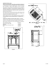
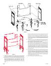
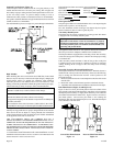
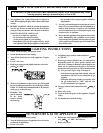
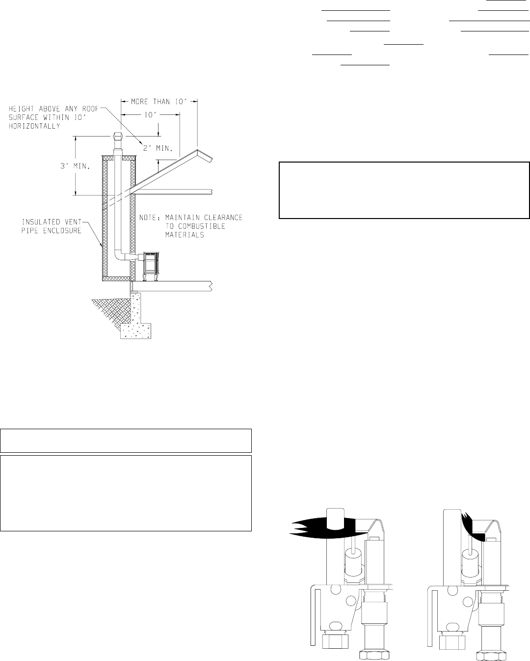
Insulated Vent Enclosure (Figure 12)
Vented fireplace heaters installed with the vent going directly to the
outside and above the eaves can cause poor venting. The cold pipe will
have a delay in proper venting and cause the fireplace heater to shut "off"
by the vent safety switch. To prevent delayed venting as well as
condensation of flue products an insulated enclosure is recommended.
Use type B 4" (102mm) diameter vent pipe and maintain at least a one inch
(25mm) clearance to combustibles.
Use metal thimble to protect vent pipe as it passes through combustibles.
Figure 12
High Altitudes
When installing this unit at an elevation above 2000 feet (in the United
States) it may be necessary to decrease the input rating by changing the
existing burner orifice to a smaller size. Generally, input should be
reduced 4 percent for each 1000 feet above sea level. However, if the
heating value of the gas has been reduced, this general rule may not apply.
Check with local gas utility for proper orifice size identification.
APPLIES TO CANADIAN MODELS ONLY FOR PROPANE GAS.
Altitude: 0-4,500 feet (0-1370 m) without orifice change.
APPLIES TO CANADIAN MODELS ONLY FOR NATURAL GAS.
Altitude 0-2,000 feet (0-610m) without orifice change.
Cet appareil est équipé pour des altitudes compris entre 0 et 2000 pieds
(0-610m) seulement.
For installations from 610-1370 metres (2,000-4,500 ft.) the orifice
size (DMS) for natural gas is 39. See data plate for additional information.
For high altitude installations consult the local gas distributor or the
authority having jurisdiction for proper rating methods. If the installer
must convert the unit to adjust for varying altitudes, the information
sticker (illustrated below) must be filled out by the installer and adhered
to the appliance at the time of conversion.
THE CONVERSION SHALL BE CARRIED OUT BY A
MANUFACTURER'S AUTHORIZED REPRESENTATIVE IN AC-
CORDANCE WITH THE REQUIREMENTS OF THE MANUFAC-
TURER, PROVINCIAL OR TERRITORIAL AUTHORITIES HAV-
ING JURISDICTION AND IN ACCORDANCE WITH THE REQUIRE-
MENTS OF THE CAN/CGA-B141.1 OR CAN/CGA-B141.2 INSTAL-
LATION CODES.
LA CONVERSION DOIT ÊTRE EFFECTUÉE CONFORMÉMENT AUX RÉ-
GLEMENTATION PROVINCIAUX EN CAUSE ET AUX EXIGENCES DES
CODES D'INSTALLATION CAN/CGA-B149.
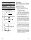
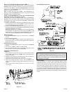
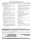
This appliance has been converted for use at an altitude of
Orifice size Manifold Pressure
Input (Btu/h) Fuel Type
Date of Conversion Converted by
Cet appareil a été converti au
Injecteur Pression à la tubulure d'alimentation
Déoit calorifique
Piezo Ignitor Button
The piezo ignitor button is located behind the valve cover. Depressing the
button causes a spark to occur at the pilot.
On a new installation with air in the gas line, depress the piezo ignitor
button a number of times in order to ignite the pilot.
Vent Safety Shutoff System
This heater must be properly connected to a venting system. This heater
is equipped with a vent safety shutoff system.
Warning:
Operation of this heater, when not connected to a properly
installed and maintained venting system or tampering with the
vent safety shutoff system, can result in carbon monoxide (CO)
poisoning and possible death.
This appliance needs fresh air for safe operation and must be installed so
there are provisions for adequate combustion and ventilation air.
This fireplace heater is equipped with a vent safety switch. The vent safety
switch will cause gas flow to the pilot to "shut off" due to improper venting
or a blocked flue.
If the vent safety switch continues to "shut off" the gas flow to the pilot
a qualified service person must be contacted to inspect for improper
venting, blockage in the vent pipe or the vent safety switch for being
defective.
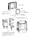
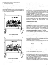
Reversible Vertical or Horizontal Draft Diverter
This fireplace heater has a reversible draft diverter. The draft diverter is
installed in the vertical position at the factory. Please use the following
steps to change the draft diverter from the vertical position to the
horizontal position.
1. Remove (8) hex-head screws located adjacent to the flue collar on the
draft diverter.
2. Rotate flue collar to the horizontal position on the draft diverter.
3. Attach flue collar to draft diverter with (8) hex-head screws from Step 1.
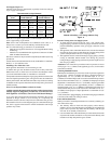
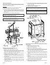
Pilot Flame Pattern (Figure 13 and Figure 14)
Figure 13 shows a correct pilot flame pattern. The correct flame will be
blue and will extend beyond the thermopile. The flame will surround the
thermopile just below the tip. A slight yellow flame may occur where the
pilot flame and main burner flame meet. Figure 14 shows an incorrect
pilot flame pattern. The incorrect pilot flame is not touching the
thermopile. This will cause the thermopile to cool. When the thermopile
cools, the heater will shut down.
Correct Pilot Flame Pattern Incorrect Pilot Flame Pattern
Figure 13 Figure 14