


R-3450 Page 13
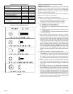
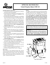
General Glass Information
Only glass approved for use in Empire Comfort Systems, Inc. fireplaces
may be used for replacement. The glass replacement should be done by
a licensed or qualified service person.
WARNING:
1. The use of substitute glass will void all product warranties.
2. Care must be taken to avoid breakage of the glass.
3. Under no circumstances should this appliance be operated without the
glass front or with a broken glass front. Replacement of the glass (with
gasket) as supplied by the manufacturer should be done by a qualified
service person.
4. Do not abuse the glass by striking or hitting the glass.
WARNING: Do not use abrasive cleaners on glass. Do not
attempt to clean glass when glass is hot.
Failure to follow these warnings could cause a serious safety issue to the
operator, such as fire or other serious conditions.
A replacement glazing/frame assembly shall be replaced as a complete
unit as supplied by Empire Comfort Systems, Inc.
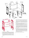
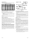
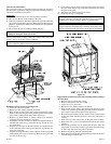
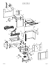
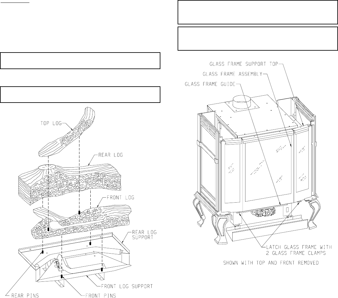
Figure 19
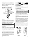
Installation of Logs (Figure 19 and Figure 20 )
1. Lower valve cover on firebox.
2. Release two door latches at bottom of firebox.
3. Grasp bottom of glass frame, pull forward until bottom of glass
frame is removed from glass frame guide and pull downward until
glass frame is removed from glass frame support top.
4. Remove logs from interior of firebox. Remove all protective
packaging from logs and interior of firebox.
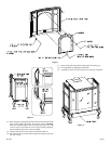
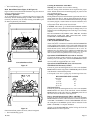
5. Align the two rear pins on the base with the two alignment holes on
the underside of the rear log. Place the rear log onto the two rear
pins on the base.
6. Align the two front pins on the base with the two alignment holes
on the underside of the front log. Place the front log onto the two
front pins on the base.
7. Align the two alignment holes on the underside of the top log with
the alignment pins on the top of front log. Place the top log onto the
two pins on the front log.
8. Grasp bottom of glass frame, push upward and insert glass frame
into glass frame support top, push inward and insert glass frame
into glass frame guide.
9. Attach two door latches to bottom of firebox.
10. Installation of logs is completed.
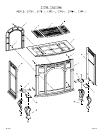
Warning: Failure to position the parts in accordance with this
diagram or failure to use only parts specifically approved with this
appliance may result in property damage or personal injury.
Avertissement: Risque de dommages ou de blessures si les pièces ne
sont pas installées conformément à ce schéma et ou si de pièces autres
que celles spécifiquement approuvées avec cet appareil sont utilisées.
Figure 20
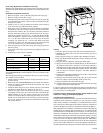
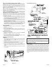
Replacement of Gasket on Glass Frame Assembly and Front Flange
on Inner Body
1. Remove casing top from outer casing.
2. Remove casing front from outer casing.
3. Lower valve cover on firebox.
4. Release two door latches at bottom of firebox.
5. Grasp bottom of glass frame, pull forward until bottom of glass
frame is removed from glass frame guide and pull downward until
glass frame is removed from glass frame support top.
6. Place glass frame assembly on a non-abrasive surface. The exterior
of the glass frame assembly should be facing the non-abrasive
surface.
7. Remove the (6) screws and (6) nuts on the glass frame assembly.
8. Remove the (2) 1" x 13-3/4" divider brackets from the glass frame
assembly.
9. Remove the gasket that is to be replaced on the glass frame and
front flange on inner body. Clean the glass frame and front flange
on inner body before the new gasket is attached.
10. Remove the backing material from the gasket.
11. Place the gasket around each opening in the glass frame and around
the front flange on inner body.