


R-3450 Page 11
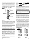
If pilot flame pattern is incorrect, as shown in Figure 14
• See Troubleshooting, page 16.
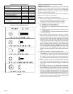
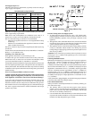
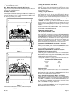
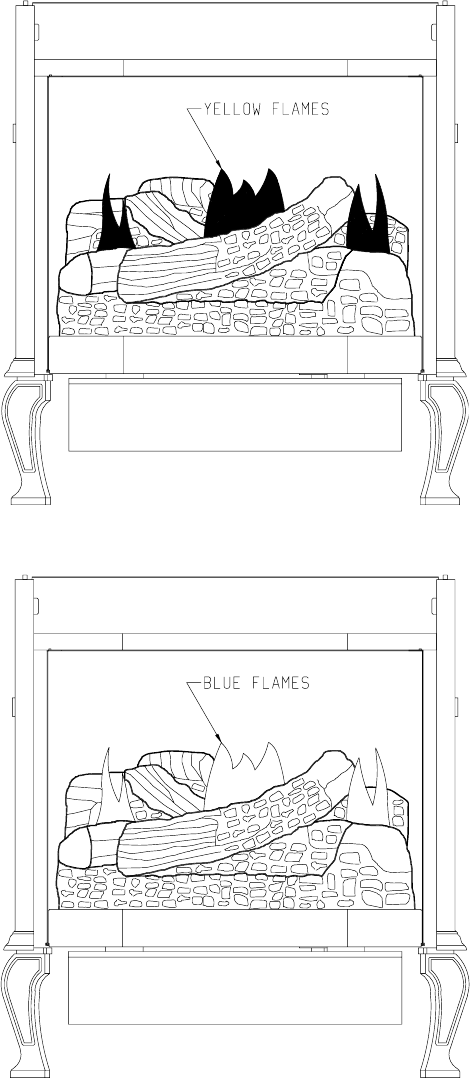
Main Burner Flame Pattern (Figure 15 and Figure 16)
Figure 15 shows a correct main burner flame pattern. Figure 16 shows an
incorrect main burner flame pattern.
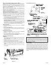
Air Shutter Adjustment
An air shutter adjusting screw is located on the exterior, bottom of the
inner body. Screw air shutter adjusting screw IN to close air shutter top
(increase yellow flame). Screw air shutter adjusting screw OUT to open
air shutter top (decrease yellow flame).
Correct Main Burner Flame
Figure 15
Incorrect Main Burner Flame
Figure 16
If main burner flame pattern is incorrect, as shown in Figure 16
• See Troubleshooting, page 16.
Cleaning and Maintenance / Main Burner
Warning: Turn off heater and let cool before cleaning
After use, cleaning of the main burner may be required for the proper
flame. The main burner may be cleaned by applying air pressure to the
ports on the main burner.
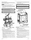
Cleaning the Log Set and Firebox
During the annual inspection and maintenance appointment, the service
person should clean dust, lint, and any light accumulation from the logs
and the firebox area. An extra-soft brush should be used on the logs as they
are extremely fragile; a vacuum cleaner may be used on the firebox. If at
any time the logs cannot be removed or installed without forcing, the
cause must be found. The logs must never be forced.
CAUTION: The ceramic logs are durable when handled and installed
properly. However, they are delicate and may be damaged easily if not
handled with care. Handling damage to the ceramic logs is not covered by
warranty.
DO NOT HANDLE LOGS WHILE THEY ARE HOT. ALLOW
PLENTY OF TIME FOR THE APPLIANCE TO COOL
COMPLETELY BEFORE HANDLING.
OPERATING INSTRUCTIONS
CIBV-30 ON/OFF/REMOTE Switch
CIBV-30 is equipped with an ON/OFF/REMOTE switch which is located
on the wiring chase. A wire harness is attached to the ON/OFF/REMOTE
switch. The red, black and green (wires) female push-ons attach to the
ON/OFF/REMOTE switch. At the opposite end of the wire harness, the
black and green (wires) female push-ons attach to the gas valve. An
additional green wire and the red wire, which are stripped and bare, will
attach to the 750 millivolt wall thermostat accessory, or, to one of the
other accessories that can be purchased for use with your log set.
Operation of ON/OFF/REMOTE Switch with no Accessories
To ignite main burner, turn the control knob on the gas valve from the
PILOT position to the ON position. Turn the ON/OFF/REMOTE switch
from the OFF position to the ON position. The additional green wire and
red wire, which are stripped and bare are not used.
Operation of ON/OFF/REMOTE Switch with Accessories
750 Millivolt Wall Thermostat, GWSG-T
Connect the green and red, stripped and bare, wires on the ON/OFF/
REMOTE switch wire harness to the wall thermostat. Turn the ON/OFF/
REMOTE switch on the wiring chase to the REMOTE position. Set the
wall thermostat to the desired temperature.
It is important to use wire of a gauge proper for the length of the wire:
RECOMMENDED WIRE GAUGES
Maximum Wire
Length Gauge
1' to 10' 18
10' to 25' 16
25' to 35' 14
Wall Switch, FWS-1
Connect the green and red, stripped and bare, wires on the ON/OFF/
REMOTE switch wire harness to the wall switch. Turn the ON/OFF/
REMOTE switch on the wiring chase to the REMOTE position. Pivot
the rocker switch on the FWS-1 to the ON position.
Battery Operated Remote Control, FRBC-1 and FRBTC-1
Connect the green and red, stripped and bare, wires on the ON/OFF/
REMOTE switch wire harness to the remote receiver that is a component
in the FRBC-1 and FRBTC-1. Turn the ON/OFF/REMOTE switch on
the wiring chase to the REMOTE position. Follow instructions in the
FRBC-1 and FRBTC-1 to complete installation.
Note: If batteries fail in FRBC-1 or FRBTC-1, and immediate heat is
desired, turn the ON/OFF/REMOTE switch on wiring chase from the
REMOTE position to the ON position.