


R-3450 Page 7
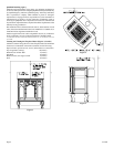
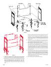
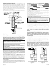
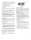
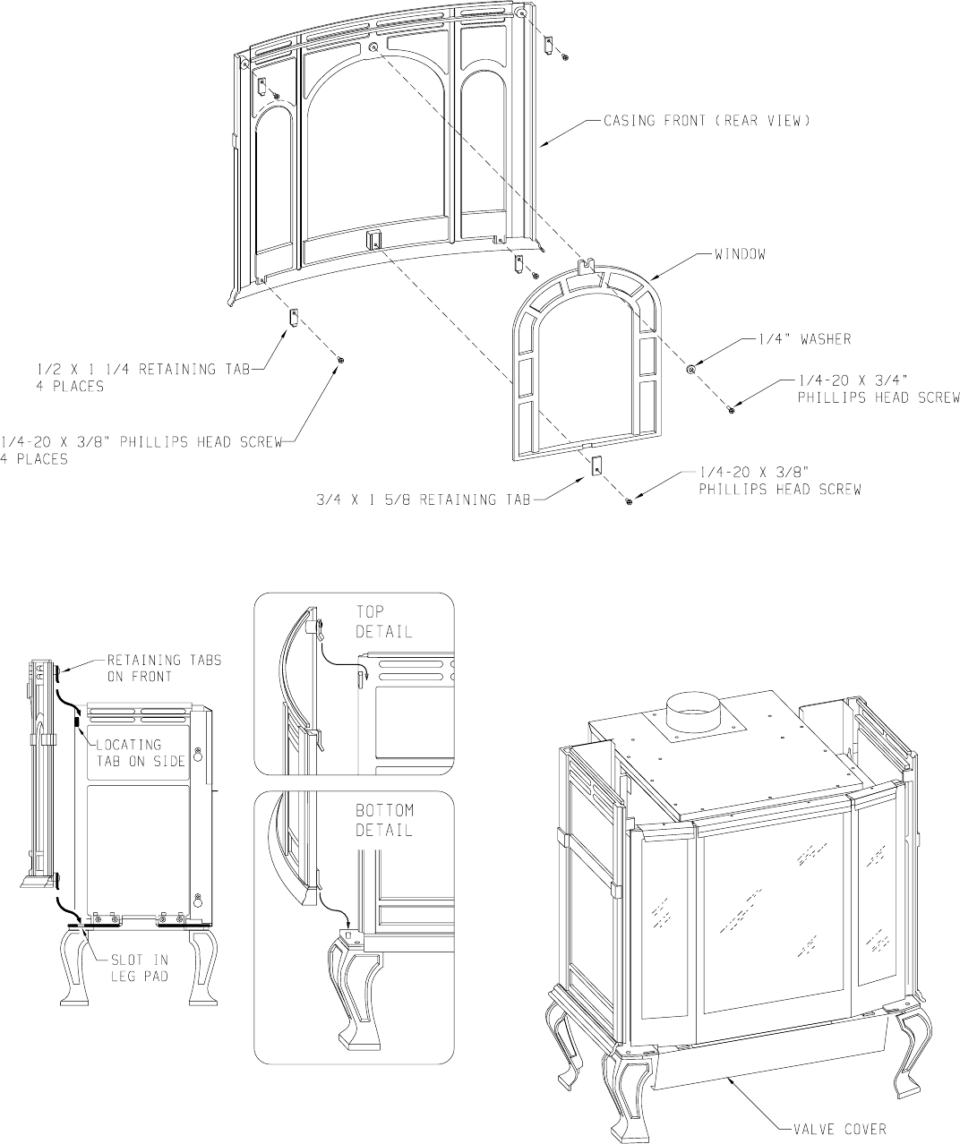
Figure 8
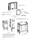
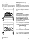
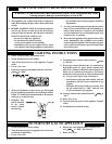
14. Refer to Figure 9, the appliance firebox can now be inserted into the
outer casing. Center the firebox in the outer casing. Attention:
Remove (1) Phillips-head screw in the top of the valve cover. The
screw is used to secure the valve cover in place during shipping.
The (1) Phillips-head screw can be discarded.
15. Attach casing front to outer casing as described in Step 11.
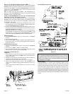
16. Place the casing top onto the outer casing. The casing top nests into
the outer casing.
17. Insert center grille, left grille and right grille into casing top.
18. Level appliance by adjusting leveling bolts.
19. Assembly of cast iron (outer casing) stove casting is completed.
Figure 9
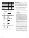
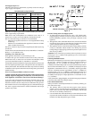
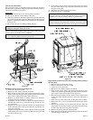
Figure 7