


Instruction Manual
760004-A
February 2002
4-26 Maintenance and Service Rosemount Analytical Inc. A Division of Emerson Process Management
Model NGA 2000 HFID
5. Inspect o-ring for damage, replace if
necessary. Install o-ring onto regu-
lator threaded shaft.
6. Insert regulator into front panel, se-
cure with mounting nut.
7. Re-attach the three tubes.
g. Purge Air Regulator
1. Remove the regulator mounting nut,
remove mounting bracket.
2. Loosen nut on tee fitting attached to
purge air flow switch.
3. Disconnect tube at elbow, remove
regulator.
4. Remove the two plugs, elbow and
male adapter fittings from the regula-
tor.
5. Replace the Teflon pipe thread tape
on the two plugs, the elbow and the
male adapter and install into replace-
ment regulator.
6. Connect tube to elbow, insert male
adapter into tee fitting.
7. Install mounting bracket onto regula-
tor, hand snug mounting nut.
8. Attach mounting bracket to front
panel, tighten regulator mounting nut.
h. Purge Air Flow Switch and Diffuser
1. Unscrew flow switch from tee fitting.
2. Replace Teflon pipe thread tape on
tee fitting.
3. Remove diffuser from flow switch and
install into replacement flow switch.
4. Install replacement flow switch.
5. Install purge switch onto tee fitting.
6. Re-connect tubes.
i. Burner Air Solenoid Valve
1. Disconnect the tube at the top elbow
fitting.
2. Disconnect the tube at the tee fitting,
remove valve analyzer module.
3. Holding the air ignite restrictor, un-
screw the solenoid valve.
4. On the solenoid valve, remove the
connector fitting.
5. Replace the Teflon pipe thread tape
on the elbow, connector and restric-
tor.
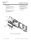
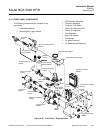
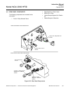
6. Verify replacement solenoid valve
wires (flat side of body) are exiting on
the same side as the COM port as
shown in Figure 4-20. If not, use an
open-end wrench to hold the N.O. hex
port while rotating body.
7. Install air ignite restrictor into N.C.
port.
8. Install elbow into COM port and con-
nector fitting into N.O. port.
9. Re-connect tubes.
j. Air Ignite Restrictor
1. On the burner air solenoid valve:
a. Disconnect the tube at the top el-
bow fitting.
b. Disconnect tube at tee fitting.
c. Lift solenoid valve from analyzer
module.
d. Disconnect tube going to air ignite
restrictor.
e. Remove restrictor from solenoid
valve.
2. Add Teflon pipe thread tape to re-
placement restrictor, install into
solenoid.
3. Re-connect tubes to restrictor, elbow
and tee fitting.