


Instruction Manual
760004-A
February 2002
Rosemount Analytical Inc. A Division of Emerson Process Management Operation 3-1
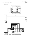
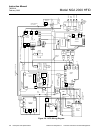
Model NGA 2000 HFID
SECTION 3
OPERATION
3-1 OVERVIEW
Prior to initial startup, the user should leak test
the module as outlined in Section 2.
For the remainder of this section, Analyzer
Module interconnection with a control module
or some interfacing component will be as-
sumed operational.
3-2 STARTUP PROCEDURE
WARNING
PRESSURIZED ENCLOSURE
This enclosure shall not be opened unless
the area is known to be free of flammable
materials or unless all devices within have
been de-energized.
Area classification for the protected enclo-
sure:
Non-Classified.
Pressurization: Type Z
Temperature Identification Number: T4A
Power shall not be restored after enclo-
sure has been opened (or loss of purge)
until enclosure has been purged for a
minimum of 6 minutes at the minimum
pressure of 689 hPa (10 psig). For safety,
the Analyzer Module should be installed in
a non-confined, ventilated space. Do not
block any of the rear panel outlets as they
are part of the safety system.
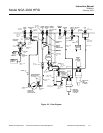
1. Connect supply gases and outlets to/from
module.
2. Turn ON the purge gas only. Perform a
leak check. Wait a minimum of 6 min-
utes.
3. Connect the LON cable(s) and the
+24VDC power cable.
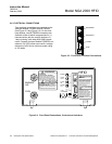
4. Turn power ON.
5. Check the 4 LEDs. The power green LED
should be illuminated. The Oven amber
LED should be blinking or on. The other
LEDs should be OFF.
6. Allow the network to initialize.
7. If the user's system contains only one
Analyzer Module, all system components,
the Controller Board and the network
"self-install" (bind together) during initial
startup. If the system contains more than
one Analyzer Module, the startup se-
quence will interrogate the network to lo-
cate and identify all components on the
network. The user will have to bind ap-
propriate combinations of components
after the startup sequence. (See Section
3-3.)
8. Check the general health of the analyzer
by reviewing the status of the Self Tests.
All “Pass” conditions should be obtained.
These test results can be found by se-
lecting the following from the Main Menu:
Technical Level Configuration, Diagnostic
Menus, Analyzer Module Diagnostics,
Self Test. All tested parameters should
indicate "Pass."
Descriptions of the tests performed follow:
• EEPROM test - Checks the EEPROM
on the Analysis Computer PCB.
• EPROM test - Checks the EPROM
on the Analysis Computer PCB.
• RAM test - Checks the RAM on the
Analysis Computer PCB.