


Instruction Manual
760004-A
February 2002
Rosemount Analytical Inc. A Division of Emerson Process Management Contents iii
Model NGA 2000 HFID
LIST OF ILLUSTRATIONS
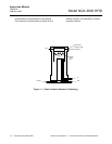
Figure 1-1. Flame Ionization Detection Technology ...........................................................................1-2
Figure 1-2. Heated Flame Ionization Detector Analyzer Module - Top View....................................1-3
Figure 2-1. Back Panel Connections ..................................................................................................2-2
Figure 2-2. Flow Diagram....................................................................................................................2-5
Figure 2-3. Front Panel Electrical Connections ..................................................................................2-6
Figure 2-4. Front Panel Connections, Controls and Indicators...........................................................2-6
Figure 2-5. HFID Outline and Mounting Dimensions ..........................................................................2-7
Figure 2-6. HFID Wiring Diagram........................................................................................................2-8
Figure 3-1. Typical Curves of Module Response vs. Pressure Setting on Fuel Pressure Regulator..3-7
Figure 3-2. Typical Curves of Module Response vs. Pressure Setting on Air Pressure Regulator.....3-7
Figure 3-3. Front Panel Torque Sequence ..........................................................................................3-8
Figure 4-1. Removal of Cover and Insulation Shield ...........................................................................4-1
Figure 4-2. Locations of Major Assemblies of the HFID ......................................................................4-2
Figure 4-3. Removal of Oven from Chassis.........................................................................................4-3
Figure 4-4. Oven Assembly..................................................................................................................4-5
Figure 4-5. Burner - Sensor, Flameout Detector, RTD Detector and Ignitor .......................................4-7
Figure 4-6. Burner/Thermal Block Disassembly ..................................................................................4-8
Figure 4-7. Burner Disassembly...........................................................................................................4-9
Figure 4-8. Burner Jets ........................................................................................................................4-10
Figure 4-9. Thermal Block – Sample RTD, Cartridge Heater and Thermostat....................................4-12
Figure 4-10. Thermal Block Assembly .................................................................................................4-13
Figure 4-11. Removing Electronics Assembly from Chassis ...............................................................4-14
Figure 4-12. Electronics Assembly – Exploded View...........................................................................4-15
Figure 4-13. Case Sensor Installation..................................................................................................4-16
Figure 4-14. Case Pressure Purge Switch Installation ........................................................................4-17
Figure 4-15. Preamp Assembly Installation .........................................................................................4-18
Figure 4-16. Fan Assembly Installation................................................................................................4-19
Figure 4-17. Flow Controller Replacement ..........................................................................................4-20
Figure 4-18. Flow Controller Assembly................................................................................................4-21
Figure 4-19. DC Power Supply Module Replacement .........................................................................4-22
Figure 4-20. Front Panel – Exploded View ..........................................................................................4-23
Figure 4-21. Accessing Front Panel Components ...............................................................................4-24
Figure 4-22. Rear Panel Components .................................................................................................4-27
LIST OF TABLES
Table 3-1. HFID Analyzer Module Alarms ..................................................................................... 3-8