


Instruction Manual
760004-A
February 2002
3-4 Operation Rosemount Analytical Inc. A Division of Emerson Process Management
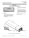
Model NGA 2000 HFID
3-4 CALIBRATION
Calibration gas setup is as follows:
1. Set oven temperature setpoint.
2. Apply regulated air at a pressure between
10 and 25 psig.
3. Allow case, oven, and sample tempera-
tures to stabilize.
4. Supply heated zero gas to sample inlet.
Adjust external flow controller or throttle
valve so that the sample inlet pressure is
between 5 and 9 psig., 7 nominal.
5. Supply heated span gas to sample input.
Repeat adjustment described in step 3.
The reading of the sample pressure,
oven, and sample temperatures should be
the same as that used during the adjust-
ment of the zero gas.
See Section 2-4c for a description of the
method for choosing calibration zero and span
gases.
To calibrate the Analyzer Module, introduce
zero gas into the SAMPLE INLET, and do the
following:
1. If more than one Analyzer Module is func-
tional and the split Run Mode display is
shown, press the DISPLAY softkey until
the desired Analyzer's Run Mode display
is acquired.
2. Press the MENUS softkey to enter the
Main Menu.
3. Verify the fuel type in the Miscellaneous
Control Parameters menu (under the
Technical Configuration menu structure,
select the following from the Main Menu:
Diagnostic menus, Analyzer Module Di-
agnostics and then Miscellaneous Control
Parameters).
4. Verify the capillary type in the Analyzer
Manufacturing Data menu (under the
Technical Configuration menu structure,
select the following from the Main Menu:
Technical Level Configuration, Service
Menus, Manufacturing Data, Analyzer
Module Data).
5. In the Calibration Gas List menu (from the
Main Menu, select Expert Controls and
Setup, Analyzer Module Setup, then Cali-
bration Gas List), enter necessary data,
including the Operational Sample Pres-
sure and the Calibration Gas HC Re-
sponse Factor. Common HC factors are:
methane (CH
4
), 1.0, ethane (C
2
H
6
), 1.90,
propane (C
3
H
8
), 3.00. These factors are
not used to compensate the reading, but
are used to select the proper preamp
sense resistor.
6. Press HOME to re-enter the Main Menu,
enter the Basic Controls menu, select de-
sired range, introduce zero gas and allow
its response to stabilize, press the ZERO
softkey to enter the Analyzer Zero menu,
press ZERO again and wait.
7. Press the SPAN softkey to enter the
Analyzer Span menu, introduce span gas
and allow its response to stabilize, press
SPAN again and wait.
8. Repeat steps 6 and 7.
9. Press the HOME softkey to re-enter the
Main Menu.
10. Press DISPLAY softkey for the Run Mode
display.
If the user is unable to calibrate the Analyzer
Module (i.e., when ZERO or SPAN is initiated,
nothing happens), several possible solutions
present themselves. One solution relates to
the use of an incorrect gas for zeroing or
spanning (e.g., using a high concentration gas
to zero or a zero gas to span the Analyzer
Module). Simply recalibrating with the appro-
priate gas(es) will not correct the problem be-
cause the ZERO OFFSET or SPAN FACTOR
has been set to an extreme value in the proc-
ess.
To remedy the problem, do the following: