


Instruction Manual
760004-A
February 2002
3-2 Operation Rosemount Analytical Inc. A Division of Emerson Process Management
Model NGA 2000 HFID
• Power supply test - Verifies that all
internal DC voltages are within the
required tolerances.
• Network test - Checks the internal
network interface.
• 20 bit ADC test - Checks the 20-bit
ADC on the Analysis Computer PCB
by sending a DC signal through the
Preamp PCB and reading the signal
back with the 20-bit ADC.
• 12 bit ADC test - Checks the 12-bit
ADC on the Analysis Computer PCB
by sending a DC signal and reading
the signal back with the 12-bit ADC.
• Power Supply PCB test - Checks
the presence of the Power Supply
PCB by activating the 3-way air sole-
noid.
• Safety PCB test - Checks the pres-
ence of the Safety PCB by sending a
command and reading it back.
• Case temperature test - Compares
the temperature read between the
Preamp temperature sensor and the
case temperature sensor. They must
be within 10°C of each other. This test
sometimes fails if the case is opened.
The sensor in the Preamp will take
longer to cool off since it is in an en-
closure. Re-running the self-test after
thermal equilibrium will produce a
positive result if the sensors are
working properly.
• Oven/Sample Temperature test -
Compares the temperature read be-
tween the sample temperature sensor
and the oven temperature sensor.
They must be within 50°C of each
other.
The self-test can be repeated at any time
by activating the TEST softkey in the Self
Test Results menu.
9. Set the desired oven setpoint in the range
of 93°C to 204°C (200°F to 400°F).
10. Wait for the Purge Air green LED to illu-
minate.
11. Introduce the remaining supply gases.
Perform leak check. (See Section 1-5
Specifications)
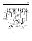
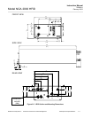
12. Set and verify the internal gas pressures.
Internal
Pressure
Regulator
Typical Operating
Pressures
Burner Air
965 to 1103 hPa-gauge
(14 to 16 psig)
Fuel
1516 to 1723 hPa-gauge
(22 to 25 psig)
Sample
(non-adjustable)
206 to 290 hPa-gauge
(3.0 to 4.0 psig)
Purge air of the following specifications
must be present:
Flow: 16 to 18 L/min.
Supply Pressure: 689 to 1378 hPa-gauge
(10 to 20 psig)
Noncompliance could cause damage to
the module. At the very least, the mod-
ule's safety system, which requires a
certain volume of purge air flowing
through the case before allowing burner
ignition, will not allow the instrument to
operate. The lowest purge air
flow/pressure setting possible during
burner operation is preferable. Thus, the
user should set the external purge air
pressure initially at 689 hPa-gauge (10
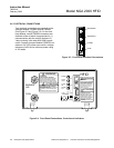
psig). Check the Miscellaneous Control
Parameters screen under Technical Di-
agnostics, and note whether the Purge
Gas (switch) variable is "ON." If it is
"OFF," increase purge air supply by
69 hPa-gauge (1 psig), and recheck the
Purge Gas variable until it reads "ON."
DO NOT EXCEED 1378 hPa-GAUGE (20
PSIG). If the maximum setting is reached,