


Instruction Manual
760004-A
February 2002
Rosemount Analytical Inc. A Division of Emerson Process Management Operation 3-5
Model NGA 2000 HFID
1. Verify that correct zero and span calibra-
tion gases are being used properly. If so,
attempt to recalibrate according to in-
structions at the beginning of Section 3-4,
ensuring that the oven, sample and case
temperatures and displayed measure-
ment reading are stable before initiating
the calibration routine. If incorrect gases
were used in the initial, failed calibration,
skip to Step 2.
2. Make the following selections from the
Main Menu: Expert Controls and Setup,
Analyzer Module Setup, then Calibration
Parameters. Disable Calibration Adjust-
ment Limits.
3. Recalibrate the analyzer module accord-
ing to instructions at the beginning of sec-
tion 3.4, ensuring that oven, sample, and
case temperatures and displayed meas-
urement reading are stable before initiat-
ing the calibration routine.
4. Enable Calibration Adjustment Limits in
the Calibration Parameters menu.
NOTE
If the range selections straddle 725 ppm,
CH
4
, the zero and span calibration for each
range must be done separately.
3-5 ROUTINE OPERATION
After case, oven, and sample temperature
stabilization, calibration, and binding, proceed
as follows:
Supply heated sample gas to SAMPLE IN-
LET. Adjust external flow controller or throttle
valve so that the sample inlet pressure is be-
tween 5 and 9 psig, 7 psig nominal. The
reading on the SAMPLE pressure gauge and
sample and oven temperatures should be the
same as that used during adjustment of the
zero and span calibration gas control.
Adjust the Range Number setting. The Ana-
lyzer Module will now automatically and con-
tinuously output the measured hydrocarbon
content of the sample. Output is in terms of
the particular hydrocarbon present in the span
gas. Note that readings obtained during op-
eration depend on the concentration of total
hydrocarbons in the sample.
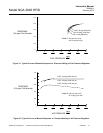
If maximum sensitivity is required from the
HFID Analyzer Module, use an optimum com-
bination of settings on the FUEL, and AIR
pressure regulators. Settings must be deter-
mined experimentally, but the curves in Fig-
ures 3-1 and 3-2 may be used as guides.
The Analyzer Module will not allow the user to
increase the upper limit of a range beyond the
"maximum range" software setting. To change
the "maximum range" value, select the fol-
lowing from the Main Menu: Technical Con-
figuration Menu, Service Menus,
Manufacturing Data, and Analyzer Module
Data. Select Maximum Range, and use the
arrow keys to scroll the indicated value. The
same applies for Minimum Range settings.
During shutdown, always turn off fuel gas first,
then the air and sample gases. The flame can
also be turned off by setting Ignition System
Enable to "Off" in the Light Flame menu (un-
der Basic Controls). Subsequently, remember
to set Ignition System Enable to "On" before
attempting to ignite the flame.
After initial startup, or startup following a pro-
longed shutdown, the Analyzer Module re-
quires about one day's continuous operation
to stabilize. For several days afterwards, cali-
brate daily. The frequency of subsequent cali-
brations can be reduced as experience
dictates, consistent with the accuracy re-
quirements of the particular application.
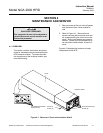
3-6 SAFETY SYSTEM
The HFID Analyzer Module safety system will
not allow ignition or continuous burner func-
tion unless the following conditions are pres-
ent:
• The internal purge gas pressure is at least
380 hPa - gauge (5.5 psig). (Monitor dis-
play message, Purge Gas Pressure in
Physical Measurements menu, for proper
setting.)
• Flow rate for purge air in is at least
16 L/min. and case pressure is greater