


35
MAN-0076 Rev 05 Millennium II
December 07, 2012
Net Safety Monitoring Inc
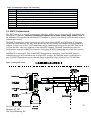
SECTION 5: Monitoring and outputs
5.1Fault monitoring
Self-testing circuitry continuously checks for problems that could prevent proper response. When power is applied to
the Millennium II Transmitter, a micro controller automatically tests the system to ensure that it is functioning
properly. During normal operation, it continuously monitors the signal from the internal sensor source. In addition, a
“watchdog” timer is maintained to ensure the program is running correctly. When a system fault is detected, the Status
LED will have a Red fast flash and the fault signal will output a 2.5 mA signal. The transmitter’s event log may be
viewed in order to distinguish the fault condition. Refer to the Event Log menu option.
Warning The fault detection circuitry does not monitor the operation of external response equipment or
external wiring to the transmitter. It is important that external equipment and wiring be checked periodically to ensure
they are operational.
5.2 Relays
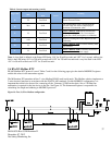
Standard electro-mechanical relays have Form C SPDT contacts rated 5 Amps at 30 VDC/ 250 VAC. There are four
physical relays; one Fault and three Alarm relays. These relays have Normally Open and Normally Closed contacts at
the output terminals. Solid State relays are Form A contacts rated 2.5 Amps at 60 VAC/DC. These relays also have one
Fault and three Alarm relays.
Alarm relays are configurable and can be assigned values; the user is allowed to assign values corresponding to desired
alarm conditions, under Relay 1, Relay 2 or Relay 3 for each channel. Relays can be selected to be ‘Energized’ or
‘De-energized’ and ‘Latching’ or ‘Non-latching’. See “relay assignment” option for reference.
NOTE: The fault relay output is not commonly used to imitate an automatic shutdown. The fault output indicates a
potential problem with the transmitter not an alarm condition.
5.3 Analog 4-20mA
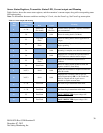
A 4-20 mA current output is used to transmit the transmitter and sensor status and fault codes to other devices. This
output can be wired for isolated or non-isolated operation. A 4.0 mA output indicates normal operation; the
transmitter’s output current range is 4.0 - 20.0 mA. For a full list of output current values and what they indicate, see
“Sensor Status Registers, Status LEDs, Current Loop, and Display Messages”