


30
MAN-0076 Rev 05 Millennium II
December 07, 2012
Net Safety Monitoring Inc
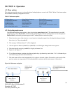
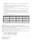
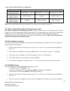
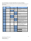
Table 4: Typical Millennium II Relay Configurations
Note 1: In above example, alarm relay 3 (RL3) will trigger whenever any alarm level 2(point 2) is reached.
Note 2: For the single channel relay model transmitter, all (3) alarm relays are available for channel 1.
4.2.7 Relay Alarm Mode setting (for Oxygen sensors only)
This option is available for detecting oxygen levels. The user is allowed to set up two Alarm points/level (normal
oxygen level is 20.9 %) under three available Alarm Modes. These Alarm Modes are: Above-Above, Below-Below
and Below-Above. The Alarm Mode chosen by the user depends on the particular application/operation. If
surrounding air is to be used for calibration, ensure that no contaminants are present. Refer to the Oxygen Sensor
Manual (MAN-0093) for detailed information.
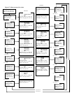
4.2.8 Select Display Language
This option allows the display language to be selected. The default language is English. There are also options for
Spanish, French, and Portuguese.
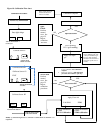
1. Enter the main menu by activating any key to get the “enter main menu” prompt then activate switch 1 to
select “yes”.
2. Activate the up key (switch 1) or down key (switch 2) until “Select Display Language?” is displayed.
3. Activate the enter key (switch 3). The default language, ‘English’, will be displayed.
4. Locate other languages by activating the enter key (switch 3).
5. Once the desired language is displayed, select “Exit” at each menu stage (sub menu and main menu).
4.2.9 MODBUS Setup
This option enables the following MODBUS parameters to be set:
• Addressing: From 001 (default) to 247
• Baud Rate: 02400 bps, 04800 bps, 09600 bps (default), 19200 bps, and 57600 bps.
• Frame Format: EVEN Parity (default), ODD Parity, NO Parity.
1. Enter the main menu by activating any key to get the “enter main menu” prompt, then activate switch 1 to
select “yes”.
2. Select the up arrow key (switch 1) or down arrow key (switch 2) until “Modbus Setup” option is displayed.
Relay Assignment Example
Channel # and selected
Alarm points (levels)
ALARM RELAY 1 (RL1)
ALARM RELAY 2 (RL2)
ALARM RELAY 3 (RL3)
CH1
POINT 1=20% lel
POINT 2=40% lel
RL1:CH1
POINT 1=20% lel
RL2:CH1
Disabled
RL3:CH1
POINT 2=40% lel
CH2
POINT 1=10 ppm
POINT 2=20 ppm
RL1:CH2
Disabled
RL2:CH2
POINT 1=10 ppm
RL3:CH2
POINT 2=20 ppm