


11
MAN-0076 Rev 05 Millennium II
December 07, 2012
Net Safety Monitoring Inc
It is the responsibility of the installer to install conduit seals where necessary, and to design conduit runs to
ensure that condensation does not accumulate and collect inside the enclosure.
2.1.2 Cable choice and guidelines
Radio Frequency Interference (RFI) can be caused by nearby electrical devices (transformers, high voltage equipment)
as well as handheld communications devices/radios, which when activated, may impede the proper functioning of the
transmitter and sensor. Selecting the right instrumentation cable and making proper grounding connections within the
junction box will reduce or eliminate interference. Visible symptoms of Radio Frequency Interference (RFI) include
inconsistent, incorrect and erratic LEL and PPM readings.
Important Wiring Guidelines
Fire and gas detection instruments are an important part of a safety alarm and shutdown system. The system is
composed of:
detection instruments
customer connected equipment
wiring
Net Safety designs and manufactures its detection equipment under rigid quality control management systems and
makes every effort to design for the harshest of industrial environments. The other components of the system – the
customer-connected equipment and wiring – are also important contributors to the overall quality and performance of
the safety system.
It is important to implement wiring that ensures the reliability and integrity of the safety system. Field wiring practices
and the choice of cable type specified vary from project to project. Poor practices and choices are often found to be the
source of unwanted system disruptions. Radio Frequency Interference (RFI) and Electro-Magnetic Interference (EMI)
are usually very powerful disruptive forces in industrial facilities and these forces act upon the system through the
wiring.
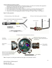
Follow the wiring specifications and guidelines in this manual carefully. The cable used should be a very high quality
instrument grade, certified for the application conditions, consisting of a rugged protective outer jacket, an overall
electrical shield of fine braided copper or metallic foil, and internal pairs or triads of foil shielded copper wire of
suitable gauge for the power conducted over the specified length.
The shields must be electrically continuous from the instrument junction box through other junction boxes and finally
to the connected equipment. The shield must be connected to a suitable ground sink as specified in the instrument
manual in order to protect the system from electrical disturbances.
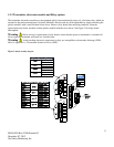
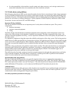
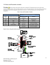
Recommended cable and guidelines
The type of cable and shielding practices are especially important when sensor is separated from transmitter via
junction box. Net Safety recommends using CSA armored instrumentation cable (ACIC 2PR 16AWG, 300V, ISOS,
PVC) when rigid (steel) conduit is not used. See Figure 5. This cable should be used between the PLC/PANEL/DCS
and the Millennium II Transmitter, as well as between the Millennium II Transmitter and junction box.
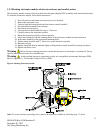
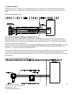
Additional notes:
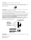
In general, communication cables and power cables should not run in parallel for any significant length, and should not
be carried in the same cable tray. Through inductance, high currents in power cables can induce significant ‘noise’ in
communication cables running parallel alongside power cables.
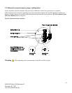
See cable preparation procedure on next page.