28
MAN-0076 Rev 05 Millennium II
December 07, 2012
Net Safety Monitoring Inc
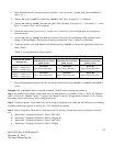
10. Apply test gas to confirm alarm level settings.
Important: Alarm Point 1 and Alarm Point 2 are values completely under the control of the user. If the user chooses,
Alarm Point 1 can be assigned a value corresponding to a high alarm condition and Alarm Point 2 assigned a value
corresponding to a low alarm condition.
To avoid confusion however, most users may want to assign Alarm Point 1 as the low alarm condition and Alarm point
2 as the high alarm condition.
4.2.5 Setting Relay options
This option allows the Alarm relay coils to be configured as energized or de-energized and latching or non-latching.
• FAULT RELAY: The Fault relay is Energized and Non-Latching. This relay is not configurable.
• ALARM RELAYS 1, 2 and 3: Factory set as De-energized and Non-Latching. These relays are configurable.
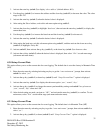
1. Enter the main menu by activating any key to get the “enter main menu” prompt, then activate switch 1 to select
“yes”.
2. Activate the up key (switch 1) or down key (switch 2) until, “Set Relay Options?” is displayed.
3. Activate the enter key (switch 3) to enter the option. The sub menu options are: ‘Fault relay’, ‘Alarm relay 1’,
‘Alarm relay 2’, ‘Alarm relay 3’.
4. Activate the down key (switch 2) or up key (switch 1) to highlight configurable Alarm relays (‘Alarm relay 1’,
‘Alarm relay 2’, ‘Alarm relay 3’).
5. Activate the enter key (switch 3) to configure the desired Alarm relay.
6. ‘Norm. Energized’ or ‘Norm.De-Energized’ will be highlighted at the top of the display screen. To change the
Energized or De-Energized setting, activate the enter key (switch 3).
7. To change the Latching or Non-Latching setting, activate the down key (switch 2) to highlight ‘Latching’ or
‘Non- Latching’, then activate the enter key (switch 3).
8. Once the desired relay settings have been made, select “Exit” at each menu stage (sub menu and main menu).
4.2.6 Relay Assignment
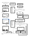
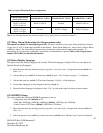
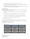
This option allows the transmitter two (2) channels (with alarm levels/points) to be configured under the three (3)
Alarm relays. When configuring under sub menu Alarm relay 1, “RL1:CH1 (Point 1, Point 2, Disabled)” and “RL1:
CH2 (Point 1, Point 2, Disabled)” is displayed. Under sub menu Alarm relay 2, “RL2:CH1 (Point 1, Point 2,
Disabled)” and “RL2:CH2 (Point 1, Point 2, Disabled)” is displayed, and under sub menu Alarm relay 3, “RL3:CH1
(Point 1, Point 2, Disabled)” and “RL3:CH2 (Point 1, Point 2, Disabled)”is displayed.
Note 1: RL1, RL2 and RL3 represents Alarm relays 1, 2 and 3. CH1 and CH2 represent channel1 and channel 2. Point
1 and Point 2 are Alarm level 1 and Alarm level 2. Alarm levels (points) are user determined and are unique to the
specific channel.
Note 2: Prior to assigning relays, configure the alarm levels (points). See Section ‘4.2.4 Viewing and setting alarm
levels (points)’, and then follow the steps and example below to configure the Alarm relays. Also see Table 3,
Example and Table 4.


