


www.desatech.com
120441-01A 5
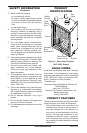
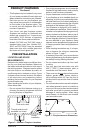
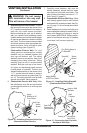
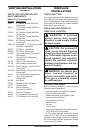
Figure 2 - Common Fireplace Locations
Flush with a wall
Through exterior wall
enclosed in a chase
Corner
installation
• This replace may be installed in any room
of your house provided all local codes and
these installation instructions are followed.
• Each time you turn on your replace, you
may notice some amount of condensation
on the inside of the replace glass. This
is normal and will disappear after 10-20
minutes of operation.
• Your direct vent gas fireplace system
(replace and venting) is a balanced and
sealed gas operating unit. It requires ap-
proximately 10-20 minutes of operating
time before the ame pattern stabilizes.
• Models DVF-36S and DVF-36H have a
standard glass inner door. Models DVF-
36SC and DVF-36HC have the standard
glass inner door with a middle glass door
and outer cool touch glass door.
PREINSTALLATION
LOCATION AND SPACE
REQUIREMENTS
Determine the safest and most efcient loca-
tion for your direct vent replace. Make sure
that rafters and wall studs are not in the way of
the venting system. Choose a location where
the heat output is not affected by drafts, air
conditioning ducts, windows or doors. Figure
2 shows some common locations. Be aware
of all restrictions and precautions before
deciding the exact location for your replace
and termination cap.
When deciding the location of your replace,
follow these rules:
• Do not connect this replace venting to a
chimney ue serving a separate solid-fuel
burning replace or appliance.
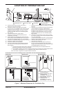
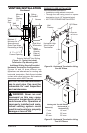
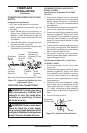
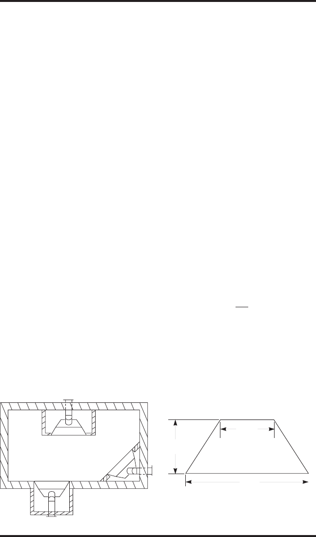
Figure 3 - Fireplace Bottom Dimensions
D
RW
FW
27
5
/
8
"
26"
43"
PRODUCT FEATURES
Continued
• Due to high temperatures, do not locate this
replace in high trafc areas, windy or drafty
areas or near furniture or draperies.
• Proper clearances must be maintained.
• If your replace is to be installed directly on
carpeting, vinyl tile or any combustible mate-
rial other than wood, it must be installed on a
metal or wood panel extending the full width
and depth of the replace (see Figure 3).
• Your replace is designed to be used in
zero clearance installations. Wall or framing
material can be placed directly against any
exterior surface on the back, sides or top of
your replace, except where standoff spac-
ers are integrally attached. If standoff spac-
ers are attached to your replace, these
spacers can be placed directly against wall
or framing material. See framing details on
page 6.
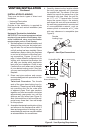
• When locating termination cap, it is impor-
tant to observe the minimum clearances
shown in Figure 7, page 7.
• If recessing into a wall, you can avoid extra
framing by positioning your replace against
an already existing framing member.
• Do not recess termination cap into a wall
or siding.
• You may paint the termination cap with
450º F (232º C) heat-resistant paint to
coordinate with the exterior nish.
• There must not be any obstruction such as
bushes, garden sheds, fences, decks or
utility buildings within 24" from the front of
the termination cap and the front of outside
air vent.
• Do not locate termination cap and outside air
vent where excessive snow or ice build up
may occur. Be sure to clear vent termination
area after snow falls to prevent accidental
blockage of venting system. When using
snow blowers, do not direct snow towards
vent termination area.