


www.desatech.com
120441-01A16
FIREPLACE
INSTALLATION
Continued
CONNECTING FIREPLACE TO GAS
SUPPLY
Installation Items Needed
• 5/16" hex socket wrench or nut-driver
• sealant (resistant to propane/LP gas, not
provided)
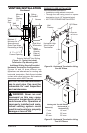
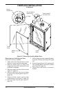
1. Route exible gas line (provided by in-
staller) from equipment shutoff valve to
replace. Route exible gas supply line
through one of the access holes on side
of replace.
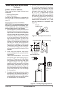
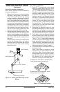
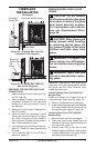
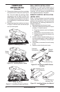
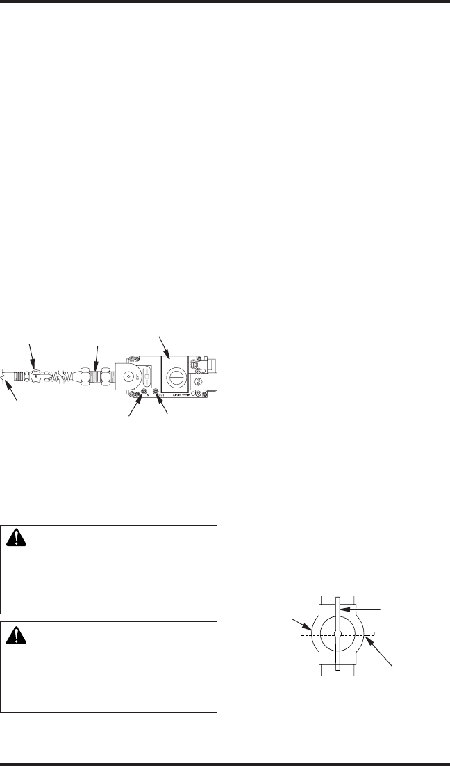
2. Attach exible gas line from gas supply to
control valve (see Figure 22).
3. Check all gas connections for leaks. See
Checking Gas Connections.
CHECKING GAS CONNECTIONS
WARNING: Test all gas piping
and connections, internal and
external to unit, for leaks after
installing or servicing. Correct
all leaks at once.
WARNING: Never use an open
ame to check for a leak. Apply
noncorrosive leak detection uid
to all joints. Bubbles forming show
a leak. Correct all leaks at once.
PRESSURE TESTING GAS SUPPLY
PIPING SYSTEM
Test Pressures In Excess Of 1/2 PSIG
(3.5 kPa)
1. Disconnect replace and its individual
equipment shutoff valve from gas supply
piping system. Pressures in excess of
1/2 psig (3.5 kPa) will damage replace
gas regulator.
2. Cap off open end of gas pipe where equip-
ment shutoff valve was connected.
3. Pressurize supply piping system by either
opening propane/LP supply tank valve
for propane/LP gas replace or opening
main gas valve located on or near gas
meter for natural gas replace or using
compressed air.
4. Check all joints of gas supply piping sys-
tem. Apply noncorrosive leak detection
uid to all joints. Bubbles forming show a
leak. Correct all leaks at once.
5. Reconnect fireplace and equipment
shutoff valve to gas supply. Check recon-
nected ttings for leaks.
Test Pressures Equal To or Less Than
1/2 PSIG (3.5 kPa)
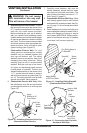
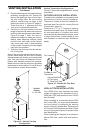
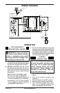
1. Close equipment shutoff valve (see
Figure 23).
2. Pressurize supply piping system by either
opening propane/LP supply tank valve
for propane/LP gas replace or opening
main gas valve located on or near gas
meter for natural gas replace or using
compressed air.
3. Check all joints from propane/LP supply
tank or gas meter to equipment shutoff
valve (see Figure 24 or Figure 25, page
17). Apply noncorrosive leak detection
uid to all joints. Bubbles forming show a
leak.
4. Correct all leaks at once.
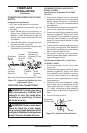
Figure 23 - Equipment Shutoff Valve
Open
Closed
Equipment
Shutoff Valve
1/2" NPT
Incoming
Gas Line
Inlet
Pressure
Tap
Outlet
Pressure
Tap
Equipment
Shutoff
Valve
Flexible
Gas Line
Do NOT
Kink
Note: Wire Connections Not Shown for Clarity
Red Surface
Indicates For
Propane/LP Use
Only
Figure 22 - Connecting Flexible Gas Line
to Electronic Valve