


www.desatech.com
120441-01A 15
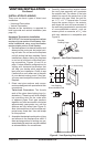
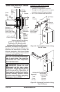
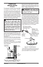
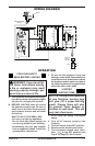
For propane/LP connection only, the installer
must supply an external regulator. The exter-
nal regulator will reduce incoming gas pres-
sure. You must reduce incoming gas pressure
to between 11" and 14" of w.c. pressure. If
you do not reduce incoming gas pressure,
replace regulator damage could occur. Install
external regulator with the vent pointing down
as shown in Figure 20. Pointing the vent down
protects it from freezing rain or sleet.
CAUTION: Use only new,
black iron or steel pipe. Inter-
nally-tinned copper tubing may
be used in certain areas. Check
your local codes. Use pipe of
1/2" diameter or greater to allow
proper gas volume to replace.
If pipe is too small, undue loss
of volume will occur.
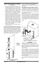
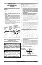
Installation must include an equipment shutoff
valve, union and plugged 1/8" NPT tap. Locate
NPT tap within reach for test gauge hook up.
NPT tap must be upstream from replace
(see Figure 21).
IMPORTANT: Install main gas valve (equip-
ment shutoff valve) in an accessible location.
The main gas valve is for turning on or shutting
off the gas to the appliance.
Check your building codes for any special
requirements for locating equipment shutoff
valve to replaces.
Figure 20 - External Regulator with Vent
Pointing Down (Propane/LP Only)
Propane/LP
Supply Tank
External
Regulator
Vent
Pointing
Down
FIREPLACE
INSTALLATION
Continued
Apply pipe joint sealant lightly to male NPT
threads. This will prevent excess sealant from
going into pipe. Excess sealant in pipe could
result in clogged replace valves.
WARNING: Use pipe joint
sealant that is resistant to liquid
petroleum (LP) gas.
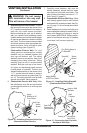
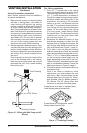
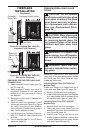
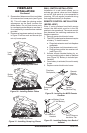
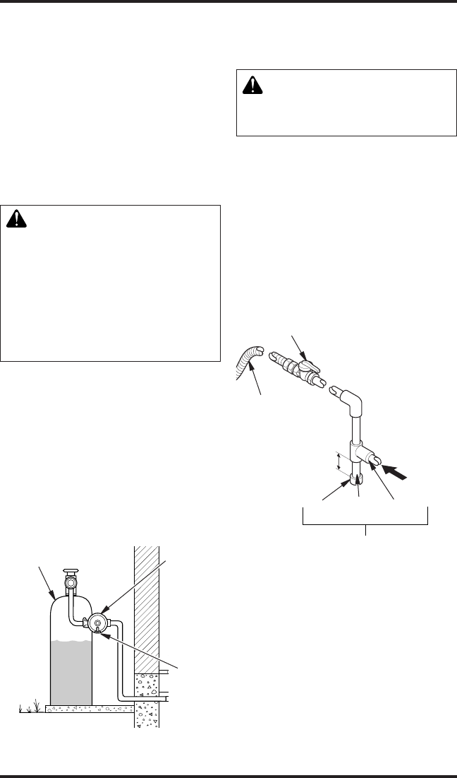
We recommend that you install a sediment
trap/drip leg in supply line as shown in Figure
21. Locate sediment trap/drip leg where it is
within reach for cleaning. Install in piping sys-
tem between fuel supply and replace. Locate
sediment trap/drip leg where trapped matter
is not likely to freeze. A sediment trap traps
moisture and contaminants. This keeps them
from going into replace gas controls. If sedi-
ment trap/drip leg is not installed or is installed
wrong, replace may not run properly.
Figure 21 - Gas Connection
CSA Design-Certied
Equipment Shutoff Valve
with 1/8" NPT Tap*
3" Minimum
Approved
Flexible
Gas Line
Cap Pipe Tee
Joint Nipple
Sediment Trap/
Drip Leg
Natural - From
Gas Meter (5.5"
W.C. to 10.5" W.C.
Pressure)
Propane/LP From
External Regulator
(11" W.C. to 14"
W.C. Pressure)
* The CSA design-certied equipment shutoff
valve may be supplied with the appliance or
you can purchase it from your retailer.