


www.desatech.com
120441-01A 13
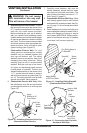
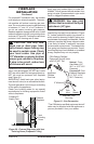
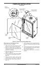
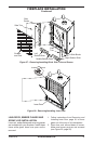
5. Place the ashing over the pipe section(s)
extending through the roof. Secure the
base of the ashing to the roof and fram-
ing with roong nails. Be sure roong
material overlaps the top edge of the
ashing as shown in Figure 16, page 12.
There must be a 1" clearance from the
vent pipe to combustible materials.
6. Continue to add pipe sections until the
height of the vent cap meets the minimum
building code requirements described in
Figure 6 on page 7. Note: You must in-
crease vent height for steep roof pitches.
Nearby trees, adjoining rooines, steep
pitched roofs and other similar factors
may cause poor draft or down-drafting
in high winds. Increasing the vent height
may solve this problem.
7. Twist-lock the vent cap onto the last sec-
tion of vent pipe.
Note: If the vent pipe passes through any oc-
cupied areas above the rst oor, including
storage spaces and closets, you must enclose
pipe. You may frame and sheetrock the en-
closure with standard construction material.
Make sure and meet the minimum allowable
clearances to combustibles. Do not ll any of
the required air spaces with insulation.
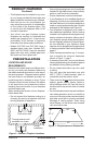
VENTING INSTALLATION
Continued
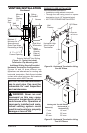
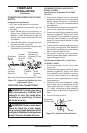
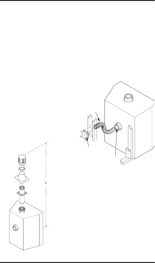
Figure 18 - Vertical Venting
Conguration
Vertical
Venting
V = 40' max.
HIGH ALTITUDE INSTALLATION
Your DESA direct vent replace has been
tested and approved for elevations from 0-
2000 feet (USA) and elevations from 0-4500
feet (Canada).
When installing at an elevation above 2000
feet (in the USA), you may need to decrease
the input rating by changing the existing
burner orice to a smaller size. Reduce input
4% for each 1000 feet above sea level. Check
with your local gas company for proper orice
size identication.
When installing this replace at an elevation
above 4500 feet, check with local authori-
ties.
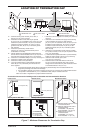
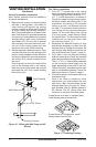
Vertical Termination Congurations
Figure 17 shows the congurations for vertical
termination.
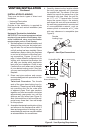
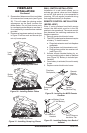
OUTSIDE AIR FLEX INSTALLATION
Outside air ex installation is required for both
horizontal and vertical venting installation.
There are 2 outside air ex kits available for
purchase (see Parts List for Venting Kits and
Components, page 14).
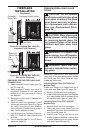
Construct a 4
1
/
2
" x 4
1
/
2
" framing or opening
on exterior wall (see Figure 19). Install outside
air vent termination in a location that would
not eventually be obstructed by bushes, snow
or other obstructions. Locate outside air vent
near replace to make ex duct installation
easier.
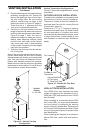
Figure 19 - Outside Air Flex Duct
Installation
Outside Air Vent
Termination
Flex Venting
Secure Both Ends
of Flex Using
Hi-Temp Duct Tape