


www.desatech.com
120441-01A10
VENTING INSTALLATION
Continued
WARNING: Do not recess
vent termination into any wall.
This will cause a re hazard.
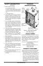
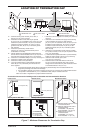
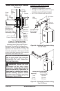
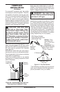
5. Noncombustible Exterior Wall: Position
the horizontal vent cap in the center of the
8
1
/
2
" round hole and attach to the exterior
wall with four wood screws provided.
Before attaching the vent cap to exterior
wall, run a bead of non-hardening mastic
(pliable sealant) around the outside edges
to make a seal between it and the outside
wall. Note: The four wood screws provided
should be replaced with appropriate fas-
teners for stucco, brick, concrete or other
types of sidings (see Figure 10).
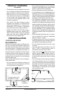
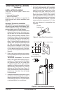
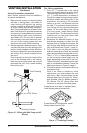
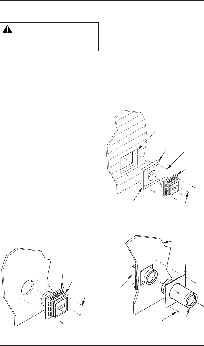
Combustible Exterior Wall: For vinyl
siding, stucco or wood exteriors, a siding
standoff may be installed between the
vent cap and exterior wall. The siding
standoff prevents excessive heat from
damaging the siding materials. Siding
material must be cut to accommodate
standoff. Bolt the vent cap to the stand-
off. Apply non-hardening mastic around
outside edge of standoff. Position the
standoff/cap assembly in the center of the
11
1
/
2
" square hole and attach to exterior
wall with wood screws provided (see Fig-
ure 11). The siding standoff must sit ush
against the exterior fascia material.
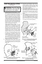
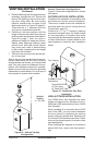
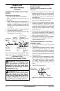
6. Combustible Exterior Wall Only: Slide
the wall restop over the vent pipe before
connecting horizontal run to vent cap (see
Figure 12).
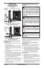
Figure 10 - Installing Horizontal Vent Cap
(Noncombustible Exterior)
Wood
Screw
Vent Cap
Figure 11 - Installing Siding Standoff
(Combustible Exterior Wall)
Cut Siding Away to
Fit Standoff
Wood
Screw
Screws
Standoff
Vent
Cap
Apply Mastic
to All Four Sides
Vent Cap
(Horizontal
Termination)
Interior Wall
Surface
Wall
Firestop
Horizontal
Vent Pipe
Figure 12 - Connecting Vent Cap with
Horizontal Vent Pipe
Screw
Apply
Mastic to All
Four Sides
7. Carefully move replace, with vent as-
sembly attached, toward wall and insert
vent pipe into horizontal termination. The
pipe overlap should be a minimum of 1
1
/
4
"
(see Figure 13, page 11).
8. Combustible Exterior Wall Only: Slide
wall restop against interior wall surface
and attach with screws provided. See Fig-
ure 13, page 11, for horizontal termination
details.
9. Place replace into position and shim with
noncombustible material if needed. Nail or
screw side anges to framing to secure
unit in place. IMPORTANT: Make sure re-
place is level before securing. If replace
is not level it will not work properly.