


www.desatech.com
120441-01A 17
FIREPLACE
INSTALLATION
Continued
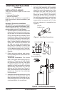
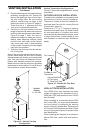
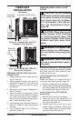
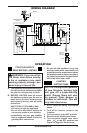
Figure 24 - Checking Gas Joints for
Propane/LP Gas Fireplace
Propane/LP
Supply Tank
Gas Valve
Equipment Shutoff Valve
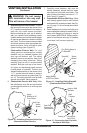
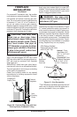
Figure 25 - Checking Gas Joints for
Natural Gas Fireplace
Gas
Meter
Gas Valve
Equipment
Shutoff Valve
PRESSURE TESTING FIREPLACE GAS
CONNECTIONS
1. Open equipment shutoff valve (see Fig-
ure 23, page 16).
2. Open propane/LP supply tank valve for
propane/LP replace or main gas valve
located on or near gas meter for natural
gas replace.
3. Make sure control knob of replace is in
the OFF position.
4. Check all joints from equipment shutoff
valve to gas valve (see Figure 24 or Figure
25). Apply noncorrosive leak detection
uid to all joints. Bubbles forming show a
leak. Correct all leaks at once.
5. Light replace (see Operating Fireplace,
page 21). Check all other internal joints
for leaks.
6. Turn off replace (see To Turn Off Gas to
Appliance, page 21).
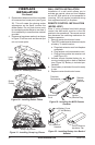
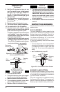
REMOVING/REPLACING GLASS
DOORS
CAUTION: Do not operate
this replace with a broken glass
door panel or without the glass
door panel securely in place.
For replacement part informa-
tion see Replacement Parts,
page 24.
CAUTION: Wear gloves and
safety glasses while handling
or removing broken glass. Do
not remove if glass is hot. Keep
children and pets away from
glass.
WARNING: If replace has
been running, turn off replace.
Let cool before removing glass
doors.
WARNING: More than one
person is required when replac-
ing glass.
Models DVF-36S and DVF-36H have only an
inner door to be removed/replaced. Models
DVF-36SC and DVF-36HC have an inner,
middle and outer door.
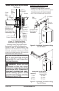
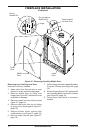
Installing Middle Door (DVF-36SC/HC
Models Only)
Middle door hangs on 2 hinges from top of
inner glass door (see Figure 26, page 18).
1. Remove middle door from packaging.
2. Angle middle door so top goes into replace
rst. Hang middle door on brackets at top
of inner door (see Figure 26, page 18).
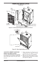
Installing Outer Door (DVF-36SC/HC
Models Only)
1. Remove outer door from packaging.
2. There are three spring loaded pins on
outer door. Set pins to the locked position
(see Figure 26, page 18).
3. Position outer door so pins line up with
mating hinges on replace. Holding door
in place, release locks on spring loaded
pins (see Figure 26, page 18).