


www.desatech.com
113110-01H18
INSTALLATION
Continued
* Purchase the optional CSA design-certied
equipment shutoff valve from your dealer.
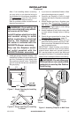
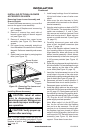
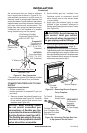
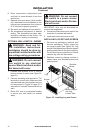
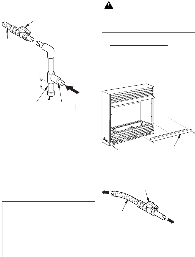
Figure 22 - Gas Connection
CSA Design-Certied
Equipment Shutoff Valve
With 1/8" NPT Tap*
3" Minimum
Approved
Flexible Gas
Line
Pipe Nipple Cap Tee Joint
From External
Regulator (11"
W.C.** to 14" W.C.
Pressure)
NATURAL
From Gas Meter
(5" W.C.** to 10.5"
W.C. Pressure)
Sediment Trap
Installation Items Needed
• Phillips screwdriver
•
sealant (resistant to propane/LP gas, not
provided)
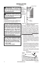
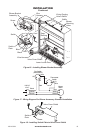
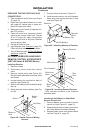
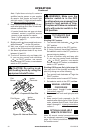
1. Remove screws that attach branch sup-
port to replace (see Figure 23). Carefully
lift up branch support and remove from
replace (see Figure 23).
-
Figure 23 - Removing Branch Support
From Fireplace
Flexible
Gas Line
Branch Support
We recommend that you install a sediment
trap in supply line as shown in Figure 22. Lo-
cate sediment trap where it is within reach for
cleaning. Install in piping system between fuel
supply and heater. Locate sediment trap where
trapped matter is not likely to freeze. A sediment
trap traps moisture and contaminants. This
keeps them from going into replace controls.
If sediment trap is not installed or is installed
wrong, replace may not run properly.
2.
Route exible gas line, included, from
fireplace control to equipment shutoff
valve through side or rear access holes
in outer casing.
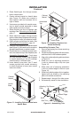
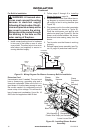
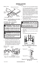
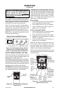
3. Apply pipe joint sealant lightly to male
threads of gas connector attached to
exible gas line/equipment shutoff valve
(see Figure 24).
4. Check all gas connections for leaks. See
Checking Gas Connections, page 19.
5. Replace branch support back into replace.
Feed exible gas line into replace base area
while replacing branch support. Make sure
the entire exible gas line is in replace base
area. Reattach branch support to replace
with screws removed in step 1.
Figure 24 - Attaching Flexible Gas Line
to Equipment Shutoff Valve
Flexible Gas Line
from Fireplace Gas
Regulator Provided
With Fireplace
To Control
Valve
Equipment
Shutoff Valve
To External
Regulator
NATURAL
To Gas Supply