


www.desatech.com
113110-01H 21
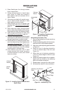
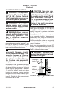
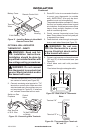
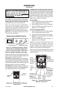
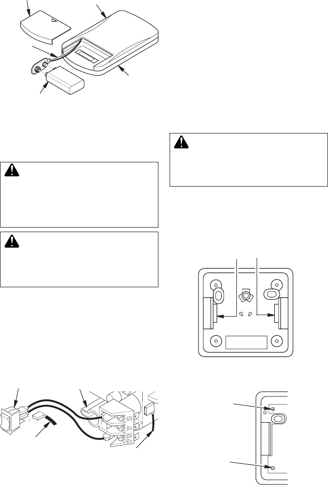
Figure 31 - Installing Battery in Hand-Held
Remote Control Unit
9-Volt Battery
Battery
Housing
Battery Cover
Terminal
Wires
Remote Control Unit
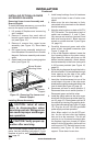
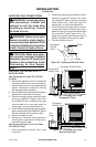
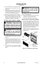
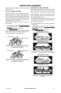
Figure 33 - Back View of Thermostat
Base
Feed wires through rectangular slots
W
R
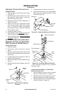
Figure 34 - Thermostat Base Terminals
“W” and “R”
Terminal “W”
Terminal “R”
3. Route 25 ft. wire to a convenient location
to mount your thermostat (no outside
wall). IMPORTANT: Wire may be short-
ened but must not be lengthened.
Thermostat should be mounted 54" above
the oor in a location where there is good
air circulation. Avoid heat sources such as
lamps, direct sunlight, replace, or heat
and air conditioning ducts.
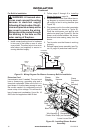
4. Gently remove thermostat cover from
base. Grasp sides of cover rmly and pull
to separate from base.
5.
Feed electrical wires through rectangular
slots on each side of base (see Figure 33).
WARNING: Do not con-
6. Connect one bare wire end to each terminal
(“W” and “R”) of the thermostat base (see
Figure 34).
7. Install base onto wall with provided
screws.
INSTALLATION
Continued
WARNING: Read and fol-
WARNING: Do not connect
this thermostat to any electrical
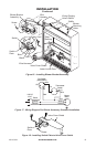
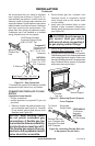
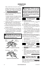
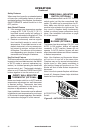
1. Connect one terminal of 25 ft. wire to bot-
tom contact of switch (see Figure 32).
2. Connect remaining wire terminal to “TH”
terminal on control valve. Make sure that
wire terminals are in the positions on your
unit as pictured in Figure 32. If wires are
not “crossed” thermostat will not work.
Figure 32 - Connecting Wire Terminals
AUTO
OFF
ON
One Terminal
of 25 ft. Wire
Switch on Gas
Fireplace
To Wall Thermostat
or Switch
Control
Valve