www.desatech.com
113110-01H 15
3
2
1
INSTALLATION
Continued
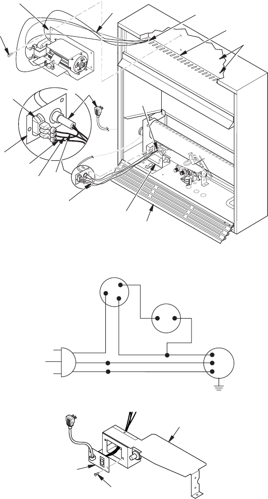
Figure 16 - Installing Blower Bracket Assembly
Wire
Harness
Blower Bracket
Assembly
Screw
Wire Harness
Switch
Bafe
Wiring Routing
Hole in Bafe
Switch
Plate
Blue
Red
Valve Cover Shield
Snap
Bushing
Black
Blower
Mounting
Holes
Lower Louver Door
Power Cord
Figure 17 - Wiring Diagram For Blower Accessory Standard Installation
Red
Red
Fan Switch
(Auto/Off/On)
Blue
Blue
Thermostat
Switch
(N.O.)
Green
White
Green
White
On
110/115
V . A.C.
Blower
Motor
Black
Off
1
2
3
Auto
Figure 18 - Installing Switch Plate to Valve Cover Shield
Valve Cover Shield
Switch
Plate
Screw


