


M48 Tank
4
3.18. If one side does not drive as effectively as the
other, test the output of the hydro pump to deter-
mine if the problem lies in the pump or the hydro
motor. By the process of elimination, if perfor-
mance is lacking, brake drag is eliminated,
adjustment is correct, and the pump is O.K.,
then the problem is the motor. Pressure and
flow tests will be used to determine if the pump
is the the source of the problem.
4. TESTING HYDRO PUMP OUTPUT
NOTE: The log splitter hydraulic test kit is used
for this set of flow and pressure tests.
4.1. Safely lift and support the rear of the M48.
4.2. If the cutting deck is currently on the unit,
remove it.
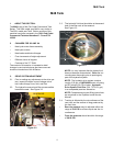
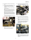
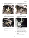
4.3. Remove the rear wheels using a 3/4” socket.
See Figure 4.3.
NOTE: The fittings on the lines that connect the
hydro pumps to the hydro motors are 1/2” JIC.
NOTE: 7/8” and 13/16” wrenches will be needed
for this test. A 1” wrench may be needed to hold
the connector that joins the JIC line connection
to the O ring connection on the hydro motor.
4.4. Thoroughly clean the area surrounding any
hydraulic fittings to be loosened or removed.
4.5. If the unit has been run recently, allow it to cool
before doing loosening any hydraulic fittings.
WARNING: Hot hydraulic fluid can cause seri-
ous burns.
WARNING: Release of pressurized hydraulic
fluid can cause serious of fatal injury.
4.6. Open the relief valve on the hydro pump that is
to be tested. This will relieve any residual
hydraulic pressure.
4.7. Confirm that the hydraulic pressure has been
relieved by rotating the brake drum / hub assem-
bly. If the it will not rotate, confirm that the brake
is released and that the brake linkage is not
bound.
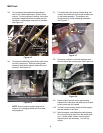
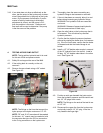
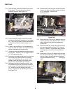
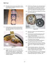
4.8. Install a 1/2” JIC double male coupler in one end
of the 18” hydraulic line in the test kit. Install a
90 deg. 1/2” JIC double male elbow in the other
end. See Figure 4.8.
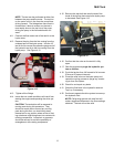
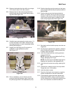
4.9. Position a catch pan beneath the hydro motor.
Have the hydraulic pressure and flow test kit and
two 1/2” JIC plugs within reach.
NOTE: The fittings on the ends of the test kit are
all 1/2” JIC.
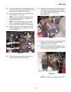
4.10. Disconnect the upper line from the hydro motor
and quickly install a 1/2” JIC plug in the line. It
only needs to be finger tight.
Figure 4.3
BRAKE DRUM
HYDRO MOTOR
HIGH PRESSURE LINES:
TOP: in-forward / out-reverse
BOTTOM: out-forward / in-reverse
18” HYDRAULIC
1/2” JIC COUPLER
ELBOW
1/2” JIC
GUAGE
PRESSURE
VALVE
METER
FLOW
Figure 4.8
LINE