


M48 Tank
24
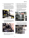
10.5. The return lines each lead back to the tank from
a tee fitting just beneath the tee fitting for the fuel
feed lines. The return fuel comes from the fuel
pressure regulator.
NOTE: If one branch of the return line becomes
crushed, kinked, or blocked, a disproportionate
amount of fuel will return the the opposite tank.
• If one fuel tank consistently empties before the
other, check the return lines.
• If this situation should occur with full tanks, an
over-flow will result.
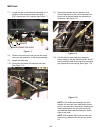
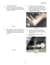
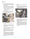
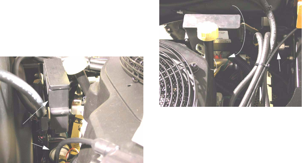
10.6. The fuel feed line leads from the tanks and tee
down to a high pressure fuel pump located
beneath the ECM. See Figure 10.6.
CAUTION: Before disconnecting any fuel line:
• Allow the engine to cool, and be sure the area is
clear of any potential fire hazards, and has ade-
quate ventilation.
• Have a catch pan handy to contain any spillage
• Relieve pressure from the any fuel lines between
the fuel pump and the fuel rail.
NOTE: The fuel pump uses the fuel as a coolant.
If the engine runs out of fuel, turn the key off
immediately. Running dry will damage the
pump.
NOTE: The fuel pump will run briefly each time
the key switch is turned on. This pressurizes the
system. If fuel pressure is absent, and the fuel
pump cannot be heard when the key switch is
turned on, the fuel pump may not be getting
electricity. Check for power before condemning
the fuel pump.
NOTE: The fuel pump is protected by an internal
60µ filter.
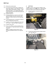
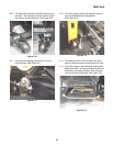
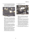
10.7. The pump sends pressurized fuel to the fuel
pressure regulator. The regulator maintains a
constant down-stream pressure of between 36
and 42 PSI. See Figure 10.7.
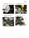
NOTE: High pressure fuel lines (SAE R9 rating)
and Oetiker style hose clamps must be used
between the fuel pump, pressure regulator, fuel
filter, and fuel injector rail.
CAUTION: Substitution of fuel system compo-
nents that are not capable of handling the pres-
sure generated by this fuel system will lead to
rapid failure of those components. Component
failure (hose, clamps, filter, etc...) in the high
pressure portion of the system poses a signifi-
cant fire hazard.
Figure 10.6
Electronic
Control
Module
Fuel pump
Figure 10.7
Fuel pump
regulator
pressure
Fuel