


M48 Tank
1
1. ABOUT THIS SECTION:
The M48 is part of the Cub Cadet Commercial Tank
Series. The 2004 model year M48 is very similar to
The 2001 model year Tank. Earlier versions of this
machine have been covered in the “2001 Cub Cadet
Commercial Technical Handbook”: Form #770-
10528.
2. CHANGES FOR ‘03 AND ‘04
• New hydro motor frame assembly
• New hydro motors
• New brakes and brake linkages
• Finer increments of height adjustment
• Different choice of engines
• Features of the 72” TANK
The content of this section is intended to detail
changes in service techniques that have occurred
since the introduction of the M Series.
3. DRIVE SYSTEM ADJUSTMENT
3.1. Prior to making any adjustments to the drive sys-
tem, inspect the hydro control linkages, drive
belt, brake linkage, tires, fluid, and filter.
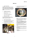
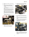
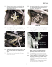
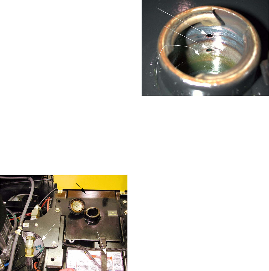
3.2. The hydraulic reservoir and filter are accessible
beneath the seat. See Figure 3.2.
Figure 3.2
RESERVOIR
OIL FILTER
BATTERY
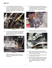
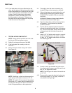
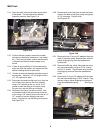
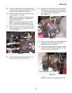
3.3. The hydraulic fluid level should be at the second
hole in the filler neck of the reservoir.
See Figure 3.3.
NOTE: It is very important that the hydraulic oil
does not become contaminated. Clean the sur-
rounding area thoroughly prior to opening any
part of the hydraulic system.
NOTE: The hydraulic drive system contains
roughly 3.25 gal. of SAE 20W50 motor oil having
an API rating of SJ-CD or better. Hydraulic
Drive System Fluid Plus (P/N: 737-3121 gal.)
is an acceptable premium alternative.
NOTE: Complete draining and filling instructions
are contained in the “Operator’s and Service
Manual”.
3.4. Tracking is effected by the circumference of the
rear tires, and the amount of drag produced by
the front tires.
• Rear tire pressure may be adjusted within the
range of 8-10 PSI to achieve equal rear tire cir-
cumference.
• Front tire pressure should be within the range
of 20-25 PSI.
Figure 3.3
FLUID LEVEL
FIRST HOLE
SECOND HOLE
M48 Tank