


M48 Tank
29
• Crank triggers are generally an all-or-nothing
proposition: they work perfectly or not at all. In
extremely rare instances, a failed crankshaft trig-
ger will not keep-up with the speed of the
engine. It will work at low speed, but cause
intermittent ignition and injector action at higher
speeds. This will result in staccato misses and
backfires.
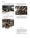
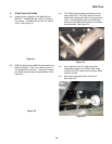
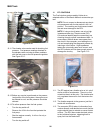
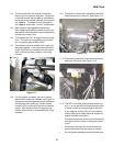
11.15. The exhaust gas oxygen (O
2) sensor contains a
palladium insert. When oxygen passes by palla-
dium, an electrical current is generated.
Depending on the amount of oxygen flowing by
the sensor, it will generate between 0.10 and
1.00 volts. See Figure 11.15.
• By measuring the amount of oxygen in the
exhaust gas, the ECU knows how much air is
passing through the engine un-burned. It can
make adjustments to the injector pulse length to
adjust the mixture until the ideal fuel air propor-
tions are reached. This ratio is known as “sto-
chiometric ratio” and is theoretically 14.7 parts
air to 1 part fuel (14.7:1).
• Adjustments the ECU makes to the fuel/air mix-
ture are the result of what is called “closed loop”
operation. The ECU is getting feedback on its
performance from the oxygen sensor, and mak-
ing adjustments based on that feedback.
• Oxygen sensors do not work below about 700
deg. F (375 deg. C). Because of this the engine
will not go into closed-loop operation until it is
warmed-up.
• Because of inconsistent gas flow at idle speed,
most engines fall out of closed-loop operation at
idle speed.
Figure 11.15
• Reaching a conclusion from the previous two
bullet points, a bad oxygen sensor will not cause
idle problems or cold-running problems.
• There is only one wire on the oxygen sensor
used in this application. It does not have a heat-
ing element in it, nor does it have a ground wire.
Some automotive applications have both of
these features. Because it does not have a
ground wire, it grounds through the body of the
sensor, and back through the engine exhaust
system.
• Oxygen sensors are susceptible to contamina-
tion from: leaded fuel, some RTV silicone seal-
ants, some cleaning solvents. Look for the
words “0
2 Sensor safe” on any of these products
to be introduced up-stream of the oxygen sen-
sor.
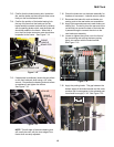
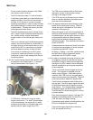
11.16. Oxygen sensors can be easily tested using a
good quality, high impedance DVOM or an oscil-
loscope.
• Engine turned off, hot sensor (normal operating
temperature) should have a resistance from the
disconnected wire to the housing or 2.0KΩ.
Cold sensor should have a resistance of 1.0MΩ.
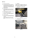
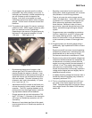
• Engine running, (above idle speed) voltage mea-
sured from the disconnected wire (remember, do
not disconnect or connect an wires while the
engine is running), should fluctuate between 0.1
volt and 1.0 volt. This roughly approximates a
sine-wave on on oscilloscope. A “blip” of the
throttle should produce a momentary increase in
voltage as the engine leans-out slightly then re-
established correct mixture.
• A steadily declining voltage that recovers from a
throttle blip without fluctuating may indicate an
improperly positioned TPS.
11.17. This is a simplified introduction to the EFI sys-
tem used on the Kohler engine found on the
TANK. Complete diagnostic and service instruc-
tions can be found in the Kohler CH26 manual,
section 5B.