


M48 Tank
9
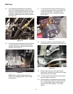
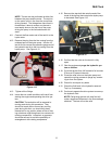
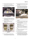
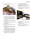
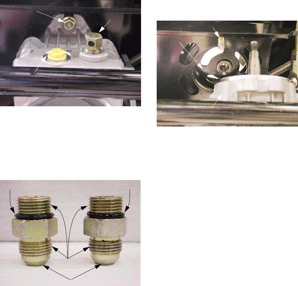
5.24. Remove the handle from the relief valve using a
7/16” wrench and a 3/16” allen wrench.
5.25. Remove the nuts from the carriage bolts that
hold the hydro pump to the hydro pump mount-
ing plate. See Figure 5.25.
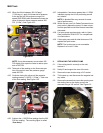
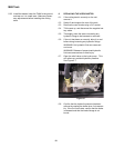
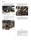
5.26. Carefully lower and remove the hydro pump. If it
is to be returned to Cub Cadet, remove the yel-
low plugs and allow it to drain completely before
packing and shipping it.
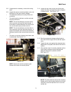
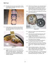
5.27. Inspect all of the fittings and O rings prior to
installation in the replacement pump.
See Figure 5.27.
5.28. Prior to installation, pour oil directly into the
pump inlet and high-pressure ports, then trans-
fer yellow plugs back to the replacement pump.
Figure 5.25
RELIEF VALVE
HANDLE REMOVE
D
FITTINGS REMOVED
AND PLUGGED
MOUNTING NUT
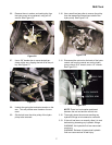
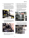
Figure 5.27
GOOD O RING
DEFORMED O RING
CHECK
THREADS
CHECK TAPERED SEATS
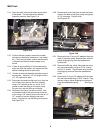
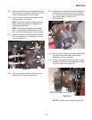
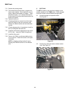
5.29. Position the pulley over the opening in the hydro
pump support plate that the pump input shaft will
pass through.
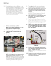
5.30. Position the pump so that the two bolts that
secure it in position line-up with the two mount-
ing ears on the pump, and the input shaft slips
into the pulley as the pump is raised up to the
hydro pump support plate. See Figure 5.30.
5.31. Start both nuts that hold the pump onto their car-
riage bolts.
5.32. As the pump is tightened into position, rotate the
pulley to align the keyways, allowing the pulley
to seat on the input shaft.
5.33. Install the fittings and lines, working quickly to
minimize fluid loss.
NOTE: Use care not to over-tighten the O ring
fittings, damaging the O rings.
NOTE: The lines may be installed finger tight to
establish their positions, then tightened fully.
5.34. Install the belt, tension arm spring, steering link-
age.
5.35. Install the fan, washer and nut to the input shaft.
Torque the nut to 240 inch/lbs.
5.36. Install the debris screen.
5.37. Check the fluid level in the reservoir, purge the
system as described in the test instructions.
5.38. If the hydraulic system has been drained and
flushed with 20W50, install a new filter and fol-
low the instructions for refilling the hydraulic sys-
tem in the “Operator’s and Service Manual”.
Figure 5.30
NEW PUMP
MOUNTING BOLT
PULLEY WITH KEY