


M48 Tank
14
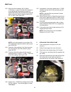
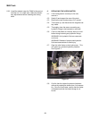
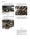
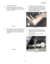
7.7. Loosen the jam nut that locks the shoulder nut in
position on the brake connector rod using a
9/16” wrench and a 3/4” wrench. See Figure 7.7.
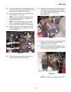
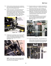
7.8. Remove the hairpin clip that secures the brake
link rod to the brake arm on the brake assembly.
7.9. Repeat on other side.
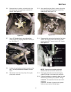
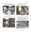
7.10. Disconnect the brake link rods (left and right).
See Figure 7.10.
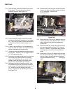
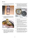
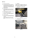
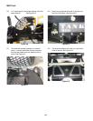
7.11. Remove the hairpin clip and clevis pin that
secures the clevis on the end of the brake con-
nector rod to the rear brake arm assembly on
both sides. See Figure 7.11.
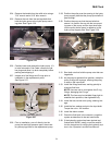
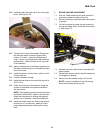
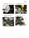
7.12. Confirm that the rear brake arm assembly
moves freely on the rear bellcrank shaft, is suffi-
ciently well lubricated, and is free from excessive
play caused by worn busings. See Figure 7.12.
NOTE: If rear brake arm assembly service is
needed, the rear bell crank shaft that the arms
pivot on can be easily removed by unbolting the
brake shaft holders, removing the cotter pins
and washers that locate the brake arm assem-
blies on the shaft.
NOTE: Both washers that fit next to each rear
brake arm go between the arm and the cotter
pin.
Figure 7.7
SHOULDER NUTS
BRAKE CONNECTOR RODS
JAM NUTS
Figure 7.10
BRAKE LINK ROD
REAR BRAKE
ARM ASSEMBLY
Figure 7.11
REAR BRAKE
ARM ASSEMBLY
BRAKE
CONNECTOR ROD
BRAKE
LINK
ROD
REAR
BELLCRANK
SHAFT
BUSHING
Figure 7.12