


M48 Tank
2
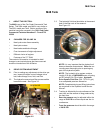
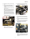
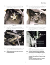
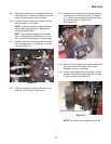
3.5. For complete brake adjustment procedures,
refer to the “Brake Adjustment” section of this
manual. For the purpose of tracking, insure that
the brake linkage bellcranks and rods are well
lubricated, not damaged, and work as intended.
See Figure 3.5.
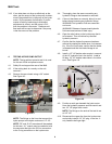
3.6. To check for brake drag, open the the relief valve
on each hydro pump. With the parking brake
released, both wheels should rotate with hand
pressure. See Figure 3.6.
NOTE: Some hydraulic system drag will be
present, but a dragging brake will be immedi-
ately apparent.
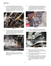
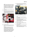
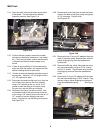
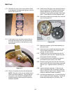
3.7. If in doubt about the source of brake drag, dis-
connect the brake link rod from the actuator arm
on the brake assembly. The actuator arm
should return to center, releasing the brakes.
See Figure 3.7.
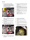
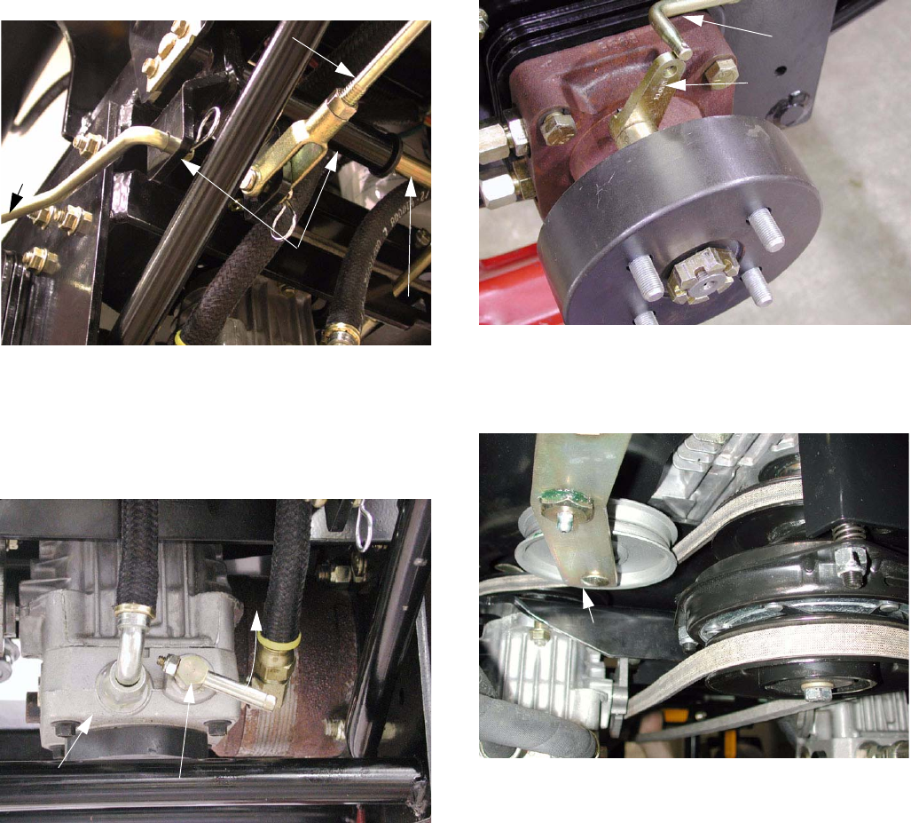
3.8. Check the condition of the belt tensioner and
belt that drives the hydro pumps. See Figure 3.8.
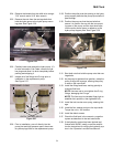
3.9. Before making neutral control and tracking
adjustments, make sure the relief valves on both
hydro pumps are fully closed.
3.10. To check neutral control, safely lift and support
the rear wheels of the Tank.
3.11. Start the engine, and release the parking brake.
Do not move the lap bars from the neutral posi-
tion. If either wheel rotates, neutral control
adjustment will be necessary. Turn off the
engine.
Figure 3.5
BRAKE CONNECTING
Link
Brake
REAR BRAKE
ARM ASSEMBLY
BELLCRANK
MOUNTING
ROD
SHAFT
Figure 3.6
HYDRO PUMP
HYDRO RELIEF VALVE
OPEN
Figure 3.7
BRAKE LINK
BRAKE ACTUATOR
ARM
Figure 3.8
DRIVE BELT
TENSIONER