


M48 Tank
12
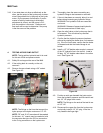
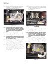
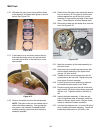
6.16. Withdraw the hydro motor, along with the three
motor spacers, and place them gently on a work
bench. See Figure 6.16.
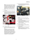
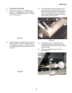
6.17. If the brake is to be removed, remove the clip
that holds the brake arm on the splined shaft,
and mark the location of the brake arm on the
splined shaft.
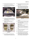
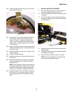
6.18. Remove the brake arm from the splined shaft.
NOTE: The Hydro motor can be ordered with or
without the brake assembly. If an appropriate
size press is not available, the dealer should
consider ordering hydro motor with the brake
assembly attached.
6.19. Safely fixture the hydro motor and brake assem-
bly in a minimum 20 Ton press so that the ram
presses against the end of the axle, and the
assembly is supported by the edge of the brake
drum. Press the drum off of the tapered shaft.
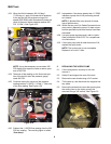
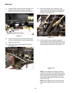
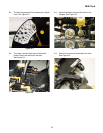
6.20. Remove the castle nut and brake drum from the
axle. See Figure 6.20.
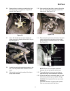
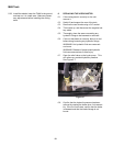
6.21. Mark the orientation of the brake assembly on
the hydro motor.
6.22. Remove the four socket head cap screws that
hold the brake assembly to the hydro motor
using a 1/4” allen wrench.
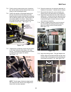
6.23. Transfer the four mounting bolts from the old
hydro motor to the new one. Replace any that
show signs of wear or damage.
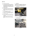
6.24. Position the three motor spacers on the bolts,
and install the hydro motor in the TANK.
6.25. Place the motor plate over the end of the bolts,
apply Loctite 242 (blue) the the bolts, and install
the four nuts. Tighten the bolts to 450-550 in.-
lbs.
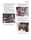
6.26. Inspect the brake assembly. If there are not
signs of significant wear or damage, install the
brake on the new hydro motor, using the match
marks to maintain the same orientation.
6.27. Use new lock washers and / or Loctite 242 (blue)
when installing the brake assembly. Torque the
socket head cap screws to 160-200 in.-lbs.
Figure 6.16
Figure 6.17
Figure 6.20
BRAKE
ASSEMBLY
ORIENTATION MARKS
(ARROW TO FITTINGS)
DRUM
BRAKE