


M48 Tank
15
7.13. Confirm that the brake bearing hub, brake han-
dle, and the brake rod that connects them move
freely on the front bellcrank shaft.
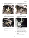
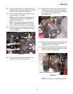
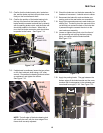
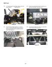
7.14. Confirm the position of the brake bearing hub:
the top of the arm that the brake rod (to the
brake handle) connects to should line-up directly
with the parking brake switch, and the brake rod
should be parallel to the frame. When this is
true, the front brake connector rods should also
be parallel to the frame. See Figure 7.14.
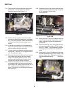
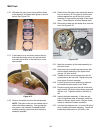
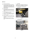
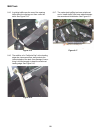
7.15. If adjustment is necklaces, loosen the two collars
on the front bellcrank shaft using a 1/8” allen
wrench. Re-position the bearing hub and collars
as necklaces, and tighten the collars.
See Figure 7.15.
NOTE: The left edge of the brake bearing hub
will usually be even with the inner edge of the
frame when correctly adjusted.
Figure 7.14
BRAKE
HANDLE
BRAKE ROD
BRAKE BEARING HUB
ARM
BRAKE
SWITCH
Figure 7.15
COLLAR
BRAKE
BEARING
HUB
FRONT
SHAFT
BELLCRANK
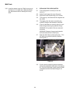
7.16. Check the brake arm on the brake assembly for
freedom of movement. It should return to center.
7.17. Reconnect the brake link rods and brake con-
necting rods to the rear brake arm assemblies.
7.18. Apply light rearward pressure to each brake con-
necting rod. The clevis pin at the rear end of the
rod should just contact the back of the hole that
it passes through to connect the clevis to the
rear brake arm assembly.
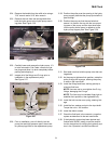
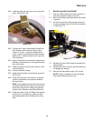
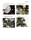
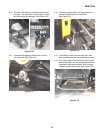
7.19. Loosen or tighten the nylock nut at the front of
the connecting rod to bring the heavy spring
lightly into contact with the brake bracket.
See Figure 7.19.
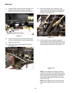
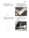
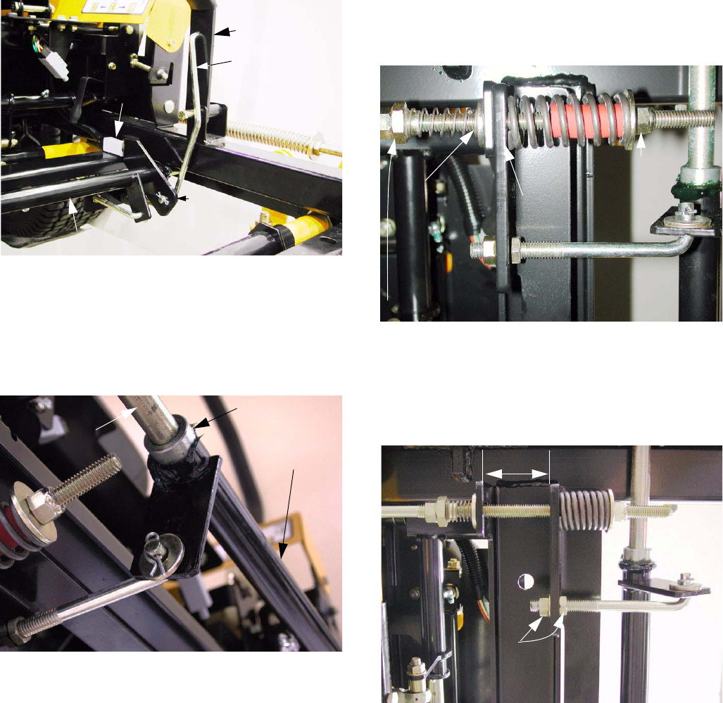
7.20. Apply the parking brake. The gap between the
bottom edges of the brake bracket and the cross
member that it rests against in the released posi-
tion should be roughly 1 3/4”. See Figure 7.20.
Figure 7.19
LIGHT
CONTACT
RETURN LINKAGE
FORCE TO
SUFFICIENT
ADJUST
HEAVY
SPRING
HERE
ADJUST RETURN
SPRING HERE
Figure 7.20
1 3/4”
ADJUST
HERE