


9
7
8) Slide or walk the assembly into its permanent position. DO NOT DROP.
9) The assembly must be level in both directions and supported around the entire base bottom. Shim and grout under
base if necessary.
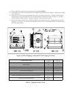
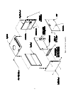
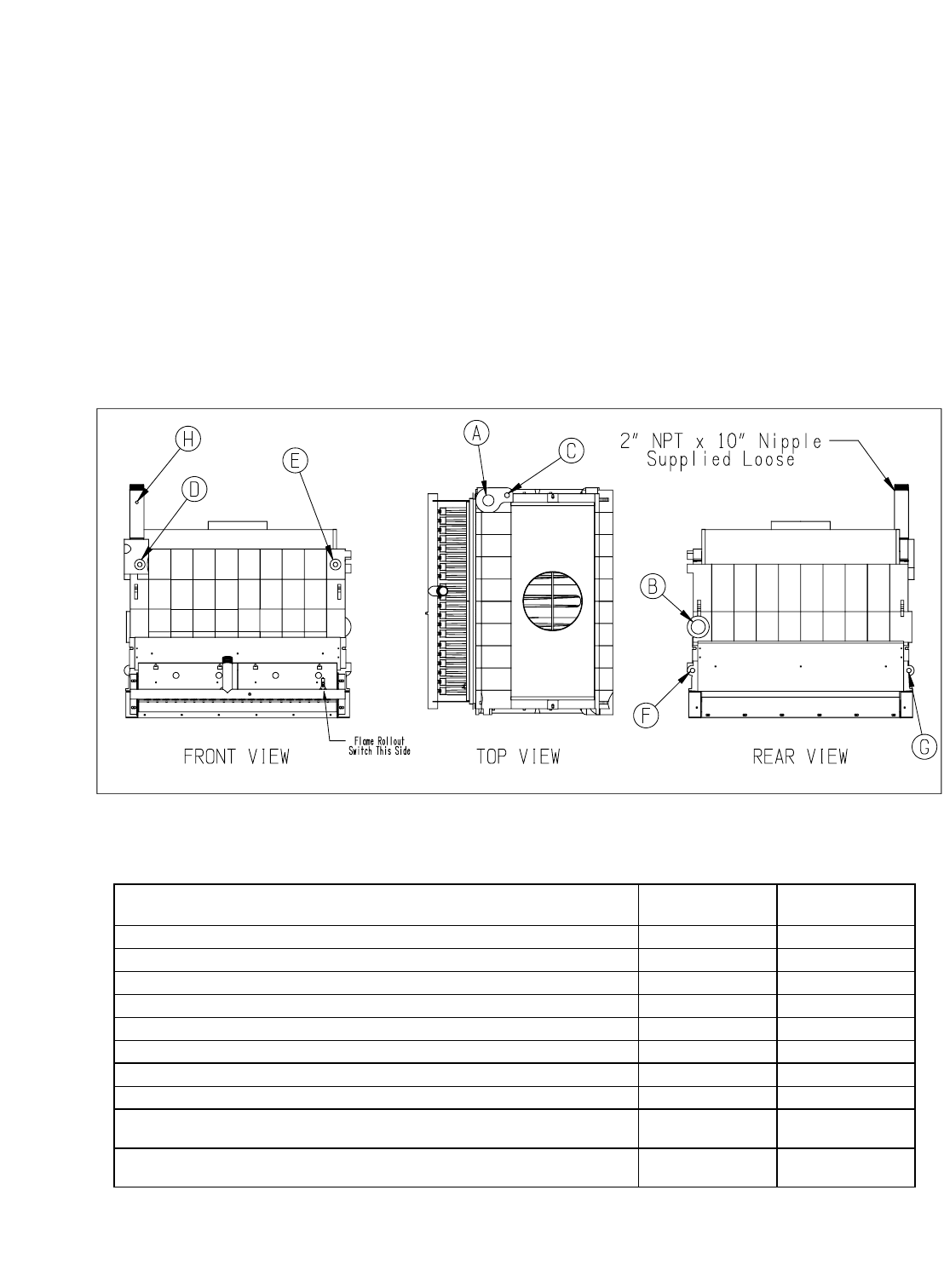
10) The flame roll-out switch has been mounted to the burner access panel at the factory. On boilers with two access
panels the panel with the mounted flame roll-out switch should be located on the right. See Figure 4. The flame
roll-out switch is a single use device - do not test with heat - the switch cannot be reset.
11) Remove the immersion well from the Combination Boiler Parts and Control Carton. Insert the immersion well in
tapping D. See Figure 4. If a second limit or operating control is used, it is recommended that it be installed in the
near boiler supply piping.
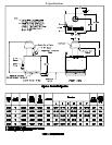
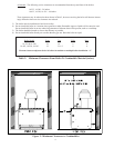
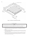
Figure 4: Boiler Shipping Arrangement With Tapping Locations
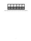
Tapping Tappi ng
Location Size (in)
Supply Piping A 2
Return Piping B 2
Pres s ure Relief Valv e C 3/4
Honeywell L4080D Limit Control D 3/4
Factory Plugged E 3/4
Washout (Factory Plugged) F 3/4
Boiler Drain Valve G 3/4
Combination Pressure / Temperature / Altitude Gauge H 1/4
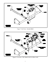
Honeywell L4006E Manual Reset Limit Control (By Others)
Boiler Supply
Piping
-
Low W ater Cut Off (By Others)
Boiler Supply
Piping
-
Component Description
Table 4: Tapping Purpose Chart