


29
27
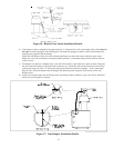
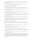
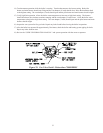
Sequence of Operation – Standard Boiler Wiring
1) All low water cut-offs and auxiliary limit controls are wired in series so that the boiler will not operate if any of
these controls are open. Under normal circumstances, only the operating control contacts will be open.
2) Upon a call for heat, the operating control will make and the vent damper (if used) will open. Simultaneously, 120
volts will be applied to the circulator.
3) 24 volts will then appear across the “24V” and “24V (GND)” terminals on the ignition modules.
4) Upon application of voltage across the “24V” and “24V (GND)” terminals, the ignition module will start an ignition
spark at the pilot and apply 24 volts across the pilot valve.
5) Once the pilot is established, the pilot flame will act as a diode, converting the AC current at the electrode to a half
wave DC current at the pilot’s ground strap. This DC current flows through the boiler to the “GND (BURNER)”
connection on the ignition module.
6) Once the ignition module detects the presence of a pilot flame, voltage is applied across the main valve, opening
the valve and establishing main flame.
7) The way in which the ignition module handles failure to establish pilot or the loss of an already established pilot
depends upon the exact ignition module supplied with the boiler. For more information on module operation,
consult the ignition module instructions supplied with the boiler or the local Crown representative.
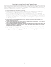
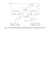
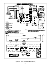
Sequence of Operation – CSD-1 Boiler Wiring
1) All low water cut-offs, limit controls, and the operating contacts are wired in series so that the boiler will not
operate if any of these controls are open. Under normal circumstances, only the operating control contacts will be
open.
2) Upon a call for heat, the operating control will make and the vent damper (if used) will open. Simultaneously, 120
volts will be applied to the circulator.
3) 24 volts will then appear across the “24V” and “24V (GND)” terminals on the ignition modules and on the
“24VAC” and “COM” terminals on the 1145-2 Daughter Board.
4) The ignition module will start an ignition spark at the pilot and apply 24 volts across the pilot valve.
5) Once a pilot is established, the pilot flame will act as a diode, converting AC current at the pilot electrode to a half
wave DC current at the pilot’s ground strap. This DC current flows through the boiler to the “GND” terminal on
the ignition module.
6) Once the ignition module detects the presence of a pilot flame, voltage is applied across the main valve, opening
the valve and establishing main flame.
7) If the pilot flame is not established during the trial for ignition period, or if the pilot signal is lost after the main
flame is established, the module will de-energize the open pilot valve and main valve (if open) and wait 5 minutes.
It will then repeat steps 4-6. If the pilot is still not established, the Alarm contacts on the ignition module will
make. This will cause the 1145-2 Daughter Board to break power to the ignition module and illuminate the red
LED on the Daughter Board. The ignition module will remain de-energized until the reset button on the daughter
board is pressed.
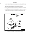
5) When a call for heat is satisfied, the damper relay coil is de-energized - closing the contacts which energize the
damper motor. This causes the damper to close. When the damper blade reaches the fully closed position, the
damper motor is de-energized.
6) Should a power failure occur, the damper blade will stop in the position it was in when power was lost. Combus-
tion can never take place unless the damper blade is in the fully open position.