34
32
WARNING
FAILURE TO FOLLOW THE FOLLOWING PROCEDURE EXACTLY COULD RESULT
IN OVER-FIRING OF THE BOILER AND A CARBON MONOXIDE HAZARD.
8) Upon initial start-up, the gas train will be filled with air. Even if the gas line has been completely purged of air, it
may take several tries for ignition before a flame is established. Once a flame has been established for the first
time, subsequent calls for burner operation should result in a flame on the first try.
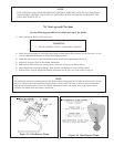
9) Observe pilot burner flame. See Figure 23. The pilot flame should be a steady medium blue flame covering
around 3/8” to ½” of the spark electrode / flame rod.
10) Inspect the main burner flames visible through the observation port in burner access panel. The flame should be
stable and mostly blue. See Figure 24. No yellow tipping should be present; however, intermittent flecks of
yellow and orange in the flame are normal.
11) Check entire gas train for leaks using soap and water or other approved leak detection method while boiler is
firing. Fix any leaks found immediately.
12) Run the gas valve safety shutdown test with the main burners firing. Disconnect ignition cable from the ignition
module on the boiler. Both the pilot burner and main burners should stop firing.
13) Check the manifold pressure and adjust if necessary. To do this, use the following procedure:
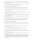
a. Connect a manometer to the inlet pressure tap on the gas valve (See Figure 25).
b. Check the inlet pressure with all gas appliances on and off. The inlet pressure at the inlet of each gas valve
must be within the following limits regardless of what combination of appliances is firing:
Inlet Press (inches w.c.) Natural Gas LP Gas
Min. 5.0 11.0
Max. 14.0 14.0
If the inlet pressure falls outside of these limits, find and correct the cause of the problem before proceeding
further.
c. Connect a manometer to the manifold (outlet) pressure tap on the gas valve on the first base module. See
Figure 25.
d. Read the manifold pressure. It should be set at:
Natural Gas LP Gas
Manifold Pressure (inches w.c.) 3.5 10.0
e. If a manifold pressure adjustment is needed, make the adjustment by turning the pressure regulator screw
(See Figure 25) clockwise to raise the pressure and counter clockwise to reduce the pressure. If a manifold
pressure adjustment is made, recheck the line pressure to be certain that it is still within acceptable limits.
f. Replace the cover screw on the regulator.
WARNING
• NEVER USE A FLAME TO CHECK FOR GAS LEAKS.
• MAKE SURE THAT THE AREA AROUND THE BOILER IS CLEAR AND FREE FROM
COMBUSTIBLE MATERIALS, GASOLINE, AND OTHER FLAMMABLE VAPORS AND LIQUIDS.


