


14
F. Control & Trim Installation
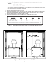
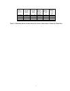
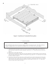
1) Table 4 shows the use of all tappings on Series 16 boilers. The tapping letter designations referenced are
shown in Figure 4. Control and trim components are as follows:
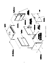
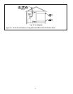
a. 4 x 4 Junction Box - Install the supplied junction box on the inside of right jacket side panel with two
8-32 x 1/2” machine screws and nuts. See Figure 6.
b.
R8285D Control Center is to be mounted to the 4 x 4 junction box. Refer to Section X for complete
wiring instructions.
c.
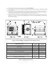
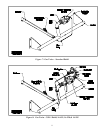
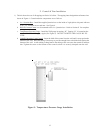
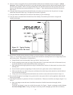
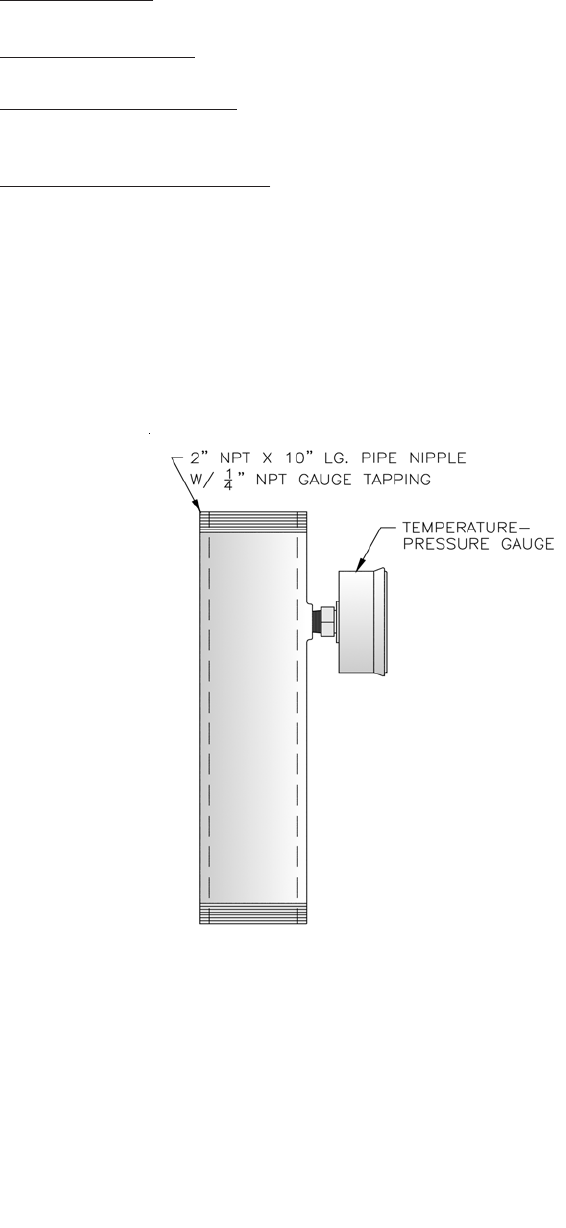
Temperature-Pressure Gauge - Install the T&P gauge in tapping “H”. Tapping “H” is located on the
supplied 2” NPT x 10” supply nipple (See Figure 9). DO NOT TIGHTEN THE GAUGE BY ITS
CASE.
d. L4080D Operating Limit Control - Insert the bulb of the control into the well until it rests against the
bottom of the well. Bend the tubing if necessary to provide enough force to hold the bulb against the
bottom of the well. Avoid making a sharp bend in the tubing as this can cause the control to malfunc-
tion. Tighten the screw on the bottom of the control so that it is securely clamped onto the well.
12
Figure 9: Temperature-Pressure Gauge Installation