


24
this low water cutoff have a manual reset function. The low water cutoff may be a float type or probe type, but must
be designed for use in a hot-water system. The low water cutoff should be piped into the boiler supply just above
the boiler with no intervening valves between it and the boiler.
Use a low water cutoff that breaks the 120 VAC supply to the boiler. Do not attempt to wire a 24-volt low water
cutoff into the boiler factory wiring.
h. Manual Reset High Limit (Required by some codes) - This control is required by ASME CSD-1 and some other
codes. Install the high limit in the boiler supply piping just beyond the boiler with no intervening valves. Set the
manual reset high limit as far above the operating limit setting as possible, but not over 240°F. Wire the control to
break the 120 VAC electrical supply to the boiler.
i.
Flow Control Valve (Required under some conditions) - The flow control valve prevents flow through the system
unless the circulator is operating. A flow control valve may be necessary on converted gravity systems to prevent
gravity circulation. Flow control valves are also used to prevent “ghost flows” in circulator zone systems through
zones that are not calling for heat.
j.
Isolation Valves (Optional) - Isolation valves are useful if the boiler must be drained, as they will eliminate having
to drain and refill the entire system.
B. Piping for Special Situations
1) Certain types of heating systems have additional requirements. Some of the more common variations follow:
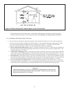
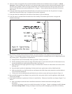
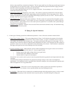
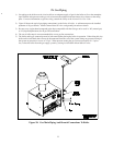
a. Large Water Volume Systems - The bypass piping shown in Figure 18 will minimize the amount of time that the
boiler operates with return temperatures below 120°F on these systems. A bypass is installed as shown to divert
some supply water directly into the return water. The bypass pipe should be the same size as the supply. The two
throttling valves shown are adjusted so that the return temperature rises above 120°F during the first few minutes of
operation. A three-way valve can be substituted for the two throttling valves shown. If the circulator is mounted on
the supply, the bypass must be on the discharge side of the circulator.
b. Systems containing oxygen - Many hydronic systems contain enough dissolved oxygen to cause severe corrosion
damage to a cast iron boiler such as the Series 16. Some examples include:
• Radiant systems that employ tubing without an oxygen barrier.
• Systems with routine additions of fresh water.
• Systems which are open to the atmosphere.
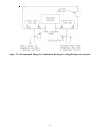
If the boiler is to be used in such a system, it must be separated from the oxygenated water being heated with a heat
exchanger.
Consult the heat exchanger manufacturer for proper heat exchanger sizing as well as flow and temperature
requirements. All components on the oxygenated side of the heat exchanger, such as the pump and expansion tank,
must be designed for use in oxygenated water.
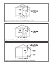
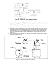
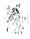
c. Piping with a Chiller - If the boiler is used in conjunction with a chiller, pipe the boiler and chiller in parallel as
shown in Figure 19. Use isolation valves to prevent chilled water from entering the boiler.
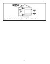
d. Air Handlers - Where the boiler is connected to air handlers through which refrigerated air passes, use flow control
valves in the boiler piping or other automatic means to prevent gravity circulation during the cooling cycle.
22