


28
26
X Control System Wiring
WARNING
All wiring and grounding must be done in accordance with the authority having jurisdiction or, in the absence of such
requirements, with the National Electrical Code (ANSI/NFPA 70).
1) Provide the boiler with a dedicated branch circuit with a fused disconnect. The minimum rating of this circuit
must be 15A.
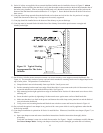
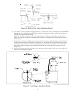
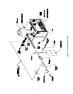
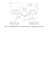
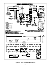
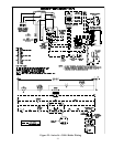
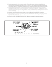
2) Locate the supplied wire harnesses and wire the boiler following the appropriate wiring diagram in Figures 21 or
22. Use 14 gauge wire for all 120 volt wiring to circulators, low water cut-offs and auxiliary manual reset hi limits
switches supplied by others. The junction box located on the inside right side jacket panel is to become the hub for
all limit and low water cut-off wiring. All 120 volt boiler wiring must be enclosed in conduit.
3) Make sure that all single pole switches and safety controls supplied by others are in the “hot” (ungrounded) side of
the circuit.
4) If a LWCO and or manual reset limit are used, wire them so that they break the 120 volt “Hot” connection to the
boiler. Do not install these devices in the 24 volt factory wiring.
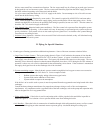
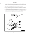
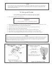
5) When wiring the optional vent damper attach the quick connect end of the supplied wire harness to the mounting
bracket on the vent and plug the quick connect into the receptacle on the vent damper. Attach the BX cable
connector located on the other end of the harness to one of the knockouts on the jacket top panel. Remove the
factory installed jumper plug from the vent damper receptacle located in the vestibule and insert the plug from the
vent damper harness into the vent damper receptacle. Cut the jumper wire on the jumper plug and discard it.
6) The 24 volt “thermostat / operating control” shown in Figures 21 and 22 is not supplied. It is the control that turns
the boiler on in response to a call for heat. Follow the thermostat / operating control instructions for placement
and wiring. Provide Class II circuit between the thermostat / operating control and the boiler. Wire the thermostat
or operating control across terminals ‘G’ and ‘R’ on the Honeywell 8285D Control Center as shown in Figures 21
and 22. Set the heat anticipator on the thermostat to match the setting listed on the ignition control.
7) Attach the line voltage or “hot” side of the circulator motor supplied by others to the yellow wire from terminal
3 on the R8222U relay located on the Honeywell R8285D Control Center. Attach the neutral side of the circulator
to the common leads in the junction box and ground as required by the circulator manufacturer. See Figures 21 and
22 for details.
Sequence of Operation – Vent Damper (If Used)
1) The vent damper is continuously powered at terminal 1.
2) On a call for heat, the damper relay coil is energized through terminal 2 if all the limits ahead of the damper are
satisfied.
3) The relay coil closes contacts which energize the damper motor, causing the damper to open.
4) When the damper blade reaches the fully open position, power is sent back to the ignition circuit through terminal 3
and the damper motor is de-energized.
DANGER
Do not attempt to reuse the jumper plug on boilers installed with vent dampers. Flue gas spillage can occur resulting
in severe injury or death.