


11
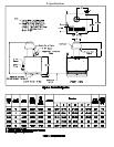
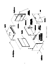
5) Lay the jacket top panel on top of the jacket side and rear panels. Locate the top of the rear jacket panel
to the inside of the jacket top panel. Align the sides of the jacket top panel to be flush with the outside
of the jacket side panels. Loosely attach the rear flange of the jacket top panel to the jacket rear panel
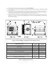
using three #10 x 1/2” sheet metal screws. On the inside front of the boiler, attach the jacket top panel to
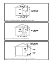
the jacket side panels with two #10 x 1/2” sheet metal screws (one per side) as shown in Figure 6.
6) Return to the loosely installed sheet metal screws and tighten all screws.
7) Attach the four door mounting hardware clips (two per side) to the front end of the left and right side
panels with #8-32 x 1/2” machine screws.
8) Attach the door knobs to the jacket door panel with 8-32 x 1/4” machine screws.
9) Mount the jacket door panel to the front of the boiler.
D. Ignition Control & Gas Valve Installation
Standard (Honeywell S8610M) Control System
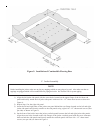
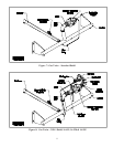
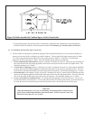
1) The standard gas valve assembly has been pre-piped with one half of a piping union and is to be connected
to the other half of the union located on the gas manifold. See Figure 7.
2) This connection must be leak tested before placing the boiler in operation. See Section IX for further
instructions on leak testing the gas piping.
3) Connect the pilot tubing from the pilot burner to the gas valve pilot tapping.
4) Attach the ignition module bracket to the jacket vestibule panel using (2) #10 x 1/2” sheet metal screws. See
Figure 6.
5) Attach the Honeywell S8610M ignition control module to the ignition module base using (4) #8 x 1/2” sheet
metal screws.
6) Connect the green ground wire from the pilot assembly to terminal number 4 (Burner GND) on the ignition
control module.
7) Connect the orange ignitor wire from the pilot assembly to terminal number 9 (SPARK) on the ignition
control module.
8) Refer to Section X for complete wiring instructions.
E. Ignition Control & Gas Valve Installation
CSD-1 Control System
1) The CSD-1 gas valve assembly has been pre-piped with one half of a piping union and is to be connected to
the other half of the union located on the gas manifold. See Figure 8.
2) This connection must be leak tested before placing the boiler in operation. See Section IX for further
instructions on leak testing the gas piping.
3) Connect the pilot tubing from the pilot burner to the pilot solenoid valve located on the CSD-1 gas valve
assembly.
4) Attach the ignition module bracket to the jacket vestibule panel using (2) #10 x 1/2” sheet metal screws. See
Figure 6.
5) Attach the UT 1003-612A ignition control module to the ignition module base using (4) #8 x 1/2” sheet
metal screws.
6) Attach the UT daughter board mounting bracket to the jacket vestibule panel using (2) #10 x 1/2” sheet
metal screws.
7) Attach the UT 1145-2 daughter board to the daughter board mounting bracket using (2) #8-32 x 1/2 screws
and hex nuts.
8) Connect the green ground wire from the pilot assembly to the terminal marked 24V GND on the ignition
control module.
9) Connect the orange ignitor wire from the pilot assembly to the terminal marked SPARK on the ignition
control module.
10) Refer to Section X for complete wiring instructions.
11) Apply the ‘CSD-1’ wiring label over top of the ‘Standard’ wiring label located on the inside door panel.
9