


56
Installation & Operation Manual
11 Maintenance
Inspect ignition and flame
sense electrodes
1. Remove the ignition and both flame sense electrodes
from the burner plate.
2. Remove any deposits accumulated on the ignition/
flame sense electrodes using sandpaper. If the
electrodes cannot be cleaned satisfactorily, replace
with new ones.
3. Replace ignition/flame sense electrodes, making
sure the gaskets are in good condition and correctly
positioned.
Check ignition ground wiring
1. Inspect boiler ground wire from the heat exchanger
access cover to ground terminal strip.
2. Verify all wiring is in good condition and securely
attached.
3. Check ground continuity of wiring using continuity
meter.
4. Replace ground wires if ground continuity is not
satisfactory.
Check all boiler wiring
1. Inspect all boiler wiring, making sure wires are in
good condition and securely attached.
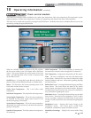
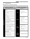
Check control settings
1. Navigate to the Setup Screen and check all settings.
See Section 1 of the Crest Service Manual. Adjust
settings if necessary. See Section 1 of the Crest
Service Manual for adjustment procedures.
2. Check settings of external limit controls (if any) and
adjust if necessary.
Perform start-up and checks
1. Start boiler and perform checks and tests specified
in Section 9 - Start-up.
2. Verify cold fill pressure is correct and that operating
pressure does not go too high.
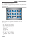
Check burner flame
1. Inspect flame through observation windows.
2. If the flame is unsatisfactory at either high fire
or low fire, remove and clean the burner. Clean
the burner thoroughly using a vacuum cleaner
or compressed air. Do not use compressed air to
clean the burner if cleaning is performed inside a
building.
• Shut down the boiler:
- Follow the “To Turn Off Gas to Appliance” instructions
for the boiler in Section 9 - Startup.
- Do not drain the boiler unless it will be exposed to
freezing temperatures. If using freeze prevention fluid
in system, do not drain.
3. Allow time for the boiler to cool to room temperature if it has
been firing.
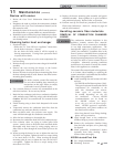
4. Remove the top access panel to remove the gas/air manifold
assembly.
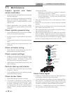
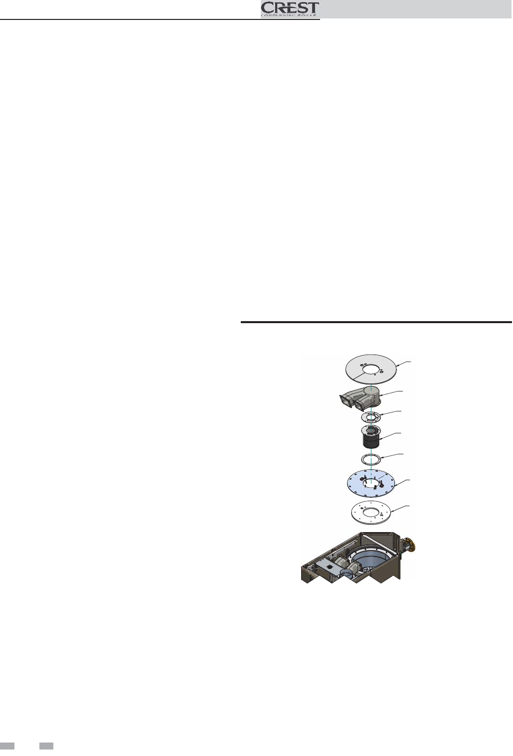
5. Remove the nuts securing the burner to the burner mounting
plate. Remove the burner (FIG. 11-2).
6. When replacing the burner, ensure gaskets are in good condition
and positioned correctly (FIG. 11-2).
7. When securing the burner, be sure to tighten the nuts, but DO
NOT over-tighten. Tighten the nuts to a torque setting of no
more than 6.2 ft.-lbs. When securing the burner mounting plate
be sure to tighten the nuts, but DO NOT over-tighten. Tighten
the nuts to a torque setting of no more than 15.5 ft.-lbs.
BURNER
ASSEMBLY
MANIFOLD
GASKET
AIR/GAS
MANIFOLD
INSULATION
BURNER
GASKET
BURNER PLATE
FIBERBOARD
Figure 11-2 Burner Assembly
Check flame signal
1. At high fire of each combustion system, the flame signal shown
on the display should be at least 10 microamps.
2. A lower flame signal may indicate a fouled or damaged flame
sense electrode. If cleaning the flame sense electrodes does
not improve, ground wiring is in good condition, and ground
continuity is satisfactory, replace the flame sense electrode.
3. See Section 3 - Troubleshooting in the Crest Service Manual for
other procedures to deal with low flame signal.