


44
Installation & Operation Manual
9 Start-up
Check flame and combustion (continued)
4. Navigate to the Service Screen from the Home Screen by
pressing the MAIN MENU button and then the SERVICE
button.
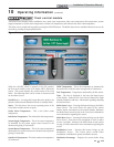
5. On the Service Screen place heater into Service Mode by
selecting the START button, then selecting Set Gas Valve
1 - High.
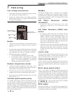
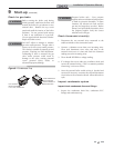
6. Insert the probe from a combustion analyzer into the hole
left by the removal of the flue temperature sensor.
7. Once the heat exchanger has modulated up to rate,
measure the combustion. The values should be in
the range listed in Table 9A below. CO levels should
be less than 200 ppm for a properly installed unit.
If the combustion is not within range reference the
Troubleshooting Section in the Crest Service Manual for
possible causes and corrective actions.
Set space heating operation
Verify space heat circulator mode
The system pump output can be programmed to never
run (OFF), run only when a space heating demand is
present (ON), or run continuously except during warm
weather shutdown (WWSD). If the boiler is not heating
an indirect HW (Hot Water) tank, it also turns on the
boiler pump. After the space heating call for heat ends,
and the system pump is programmed as ON, the system
pump continues to run for a short period of time. If the
boiler pump was running, it continues to run for a short
period of time as well. These pump delays are factory
set to 30 seconds. If different delays are desired, the
appropriate parameters in the control must be changed.
See the Crest Service Manual for a detailed explanation
of this procedure.
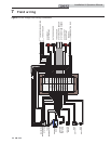
Set space heating set point temperature
During normal operation, space heating set point
temperatures can be adjusted from the Set Points Menu.
Press the following buttons to navigate to the Set Points
Menu from the Home Screen:
After pressing SETUP, the Password Screen will appear.
Entering the correct password will allow access to all
Installer Level adjustable parameters. Press ENTER
without a password to access the User Level parameters.
1. To change a set point, use the arrows to highlight a
user set point parameter and press the SELECT
button.
2. The description of the selected parameter and its
current setting will appear at the bottom of the
screen.
3. To adjust the set point, press the following
buttons to change the value being displayed:
or
4. Once the set point has been adjusted to the desired
setting press the SAVE button to change the set
point.
5. Once all the necessary adjustments have been made,
press the HOME button to return to the Home
Screen.
Note: The SAVE button must be pressed to ensure proper
programming of the controls. Failure to press the SAVE
button will require all changes to be reprogrammed.
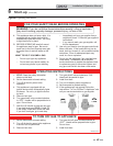
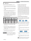
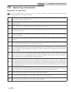
Table 9A Flue Products Chart
8. After Gas Valve 1 is set, repeat the same procedure for the
second gas train by selecting Set Gas Valve 2 - High on
the Service Screen.
9. Once the heater analysis is complete, test the safety
shutoff device by turning the manual shutoff valve to the
OFF position and ensuring that the heater shuts down
and registers an alarm. Open the manual shutoff valve
and reset the control.
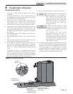
10. Turn the main power off to the boiler and replace the
flue temperature sensor into the flue pipe connection.
11. Place the boiler back into normal operation.
You must replace the flue gas temperature
sensor to prevent flue gas spillage into
the room. Failure to comply could
result in severe personal injury, death, or
substantial property damage.
ƽ WARNING
Gas
Valve
Natural Gas Propane
CO
2
O
2
CO
2
O
2
1 - High 3.5% - 5.5% 11.2% - 14.8% 5.1% - 6.8% 10.5% - 13.2%
2 - High 7.8% - 8.6% 5.6% - 7.1% 9.4% - 11.0% 4.1% - 6.6%
>>
>>