


17
Installation & Operation Manual
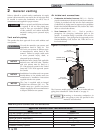
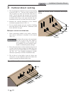
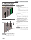
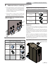
Vent, air piping and termination:
The Crest vent and air piping can be installed through the roof
or through a sidewall. Follow the procedures in this manual for
the method chosen. Refer to the information in this manual to
determine acceptable vent and air piping length.
Air contamination
Pool and laundry products and common household and hobby
products often contain fluorine or chlorine compounds. When
these chemicals pass through the boiler, they can form strong
acids. The acid can eat through the boiler wall, causing serious
damage and presenting a possible threat of flue gas spillage or
boiler water leakage into the building.
Please read the information given in Table 1A, page 9,
listing contaminants and areas likely to contain them. If
contaminating chemicals will be present near the location of the
boiler combustion air inlet, have your installer pipe the boiler
combustion air and vent to another location, per this manual.
If the boiler combustion air inlet is located
in a laundry room or pool facility, for
example, these areas will always contain
hazardous contaminants.
To prevent the potential of severe personal
injury or death, check for areas and products
listed in Table 1A, page 9 before installing
the boiler or air inlet piping.
If contaminants are found, you MUST:
• Remove products permanently.
—OR—
• Relocate air inlet and vent
terminations to other areas.
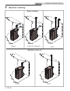
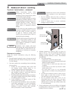
Removing from existing vent
Follow the instructions in Section 1, page 10 of this manual
when removing a boiler from an existing vent system.
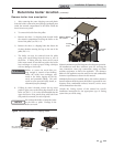
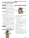
Vent and air piping
Vent and air system:
Installation must comply with local
requirements and with the National Fuel
Gas Code, NFPA 54 / ANSI Z223.1 for U.S.
installations or CSA B149.1 for Canadian
installations.
You must also install air piping from outside to the boiler
air intake adapter. The resultant installation is direct vent
(sealed combustion).
You may use any of the vent/air piping methods covered in
this manual. Do not attempt to install the Crest using any
other means.
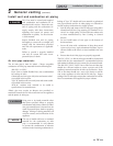
NOTICE
ƽ WARNING
ƽ WARNING
ƽ WARNING
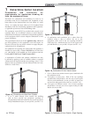
When determining equivalent combustion air and vent
length, add 5 feet (1.5m) for each 90° elbow and 3 feet (.9 m)
for each 45° elbow.
EXAMPLE: 20 feet (6 m) of pipe + (4) 90° elbows + (3) 45°
elbows = 49 equivalent feet (15 m) of piping.
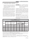
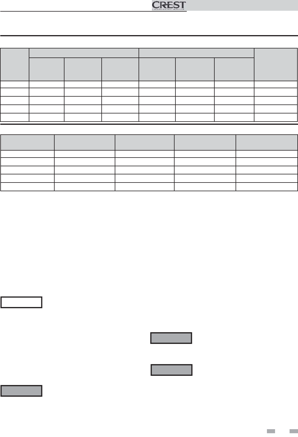
Model
AIR INLET VENT
Input
De-Rate per
25 feet of Vent
Air Intake
Diameter
Air Intake
Min. Length
Air Intake
Max. Length
Vent
Diameter
Vent
Min. Length
Vent
Max. Length
FB 1500 7" 12' 100' 7" 12' 100' 2%
FB 2000 8" 12' 100' 8" 12' 100' 2%
FB 2500 8" 12' 100' 9" 12' 100' 2%
FB 3000 10" 12' 100' 10" 12' 100' 2%
FB 3500 10" 12' 100' 10" 12' 100' 2%
Table 2B Direct Vent Minimum / Maximum Allowable Air / Vent Lengths
Model
Vent
Diameter
Vent
Min. Length
Vent
Max. Length
Input De-Rate per
25 feet of Vent
FB 1500 7" 12' 100' 1%
FB 2000 8" 12' 100' 1%
FB 2500 9" 12' 100' 1%
FB 3000 10" 12' 100' 1%
FB 3500 10" 12' 100' 1%
Table 2C Room Air Minimum / Maximum Allowable Air / Vent Lengths
2 General venting (continued)
DO NOT mix components from different
systems. The vent system could fail,
causing leakage of flue products into the
living space. Use only approved stainless
steel pipe and fittings.