


20
Installation & Operation Manual
3 Vertical direct venting
Multiple vent/air terminations
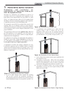
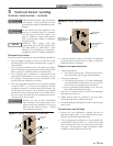
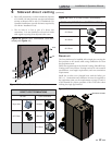
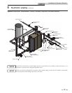
1. When terminating multiple Crest boilers, terminate
each vent/air connection as described in this manual
(FIG. 3-3).
Terminate all vent pipes at the same height
and all air pipes at the same height to
avoid recirculation of flue products and
the possibility of severe personal injury,
death, or substantial property damage.
2. Place roof penetrations to obtain minimum clearance of
12 inches (305 mm) between edge of air intake elbow and
adjacent vent pipe of another boiler for U.S. installations
(see FIG. 3-3). For Canadian installations, provide
clearances required by CSA B149.1 Installation Code.
3. The air inlet of a Crest boiler is part of a direct vent
connection. It is not classified as a forced air intake with
regard to spacing from adjacent boiler vents.
36” (914 MM)
36” (914 MM)
12”
(305 MM)
12”
(305 MM)
12”
(305 MM)
12”
(305 MM)
12”
(305 MM)
12”
(305 MM)
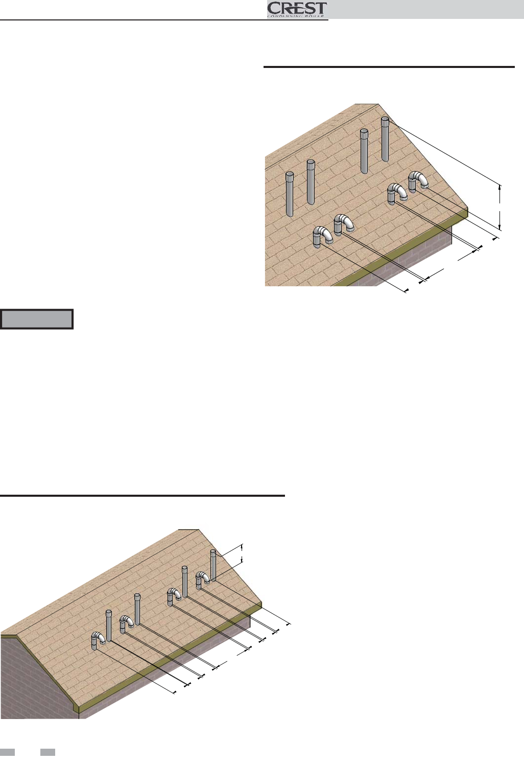
Figure 3-3 Vertical Terminations with Multiple Boilers
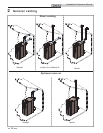
36” (914 MM)
12”
(305 MM)
36” (914 MM)
12”
(305 MM)
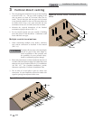
Figure 3-4 Alternate Vertical Terminations with Multiple
Boilers
ƽ WARNING
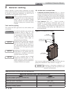
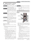
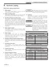
3. The vent piping must terminate in an up-turned coupling
as shown in FIG. 3-1. The top of the coupling or the
rain cap must be at least 36" (914 mm) above the air
intake. The air inlet pipe and vent pipe can be located
in any desired position on the roof, but must always be
no further than 2 feet (.6 m) apart and with the vent
termination at least 36" (914 mm) above the air intake.
4. Maintain the required dimensions of the finished
termination piping as shown in FIG. 3-1.
5. Do not extend exposed vent pipe outside of building
more than shown in this document. Condensate could
freeze and block vent pipe.