


33
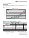
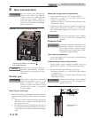
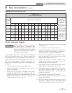
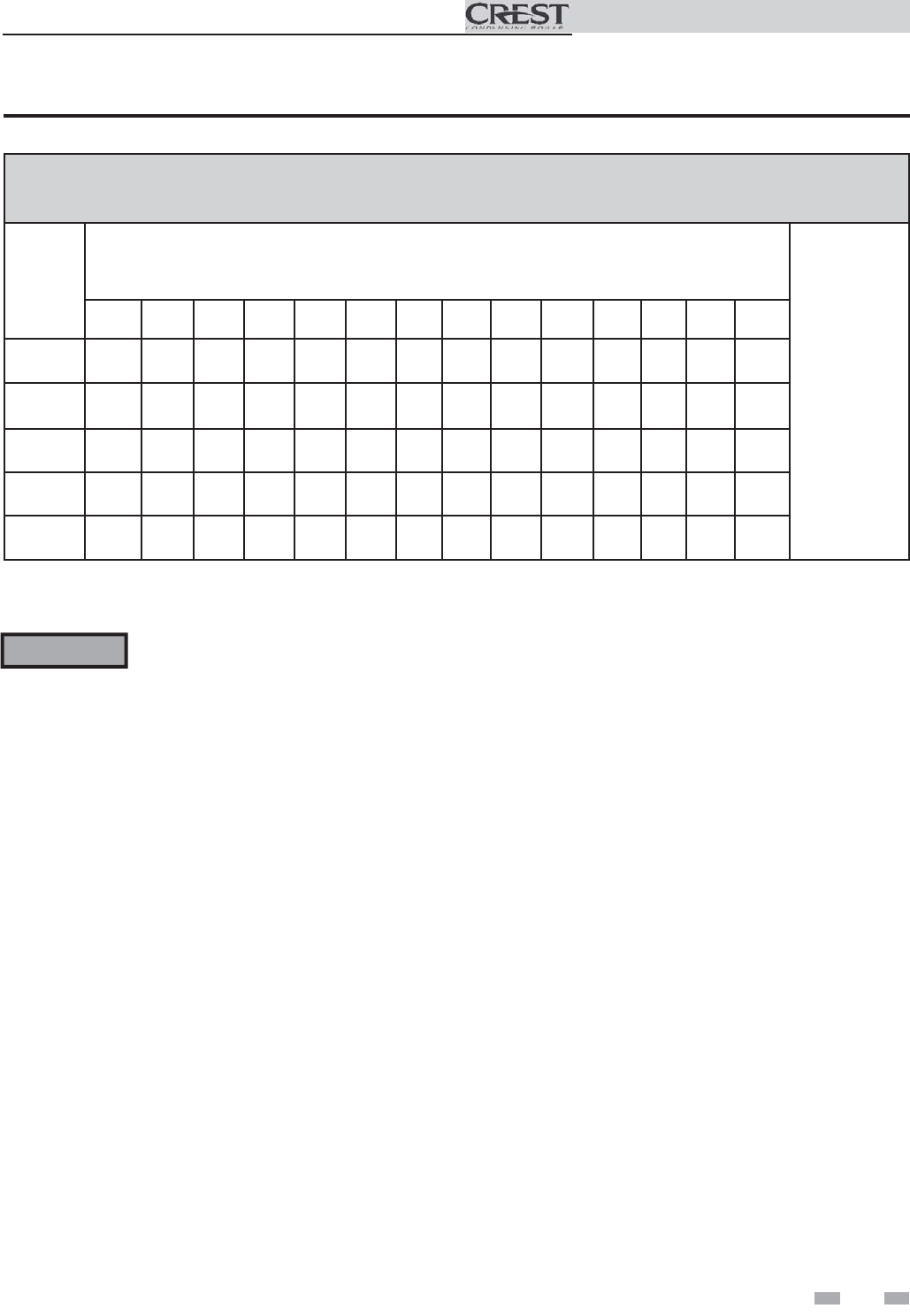
Table 6B Natural Gas Pipe Size Chart
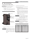
The gas piping must be sized for the proper flow and length of
pipe, to avoid excessive pressure drop. Both the gas meter and
the gas regulator must be properly sized for the total gas load.
If you experience a pressure drop greater than 1 inch w.c.
(249 Pa), the meter, regulator, or gas line is undersized or in
need of service. Perform the steps below when checking inlet
gas supply:
1. Turn the main power switch to the “OFF” position.
2. Shut off gas supply at the manual gas valve in the gas
piping to the appliance.
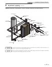
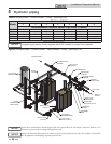
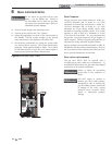
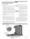
3. Remove the 1/8" pipe plug on the flange to the factory
supplied gas shutoff valve and install a suitable 1/8"
fitting (field supplied) for the manometer tubing. Place the
tubing of the manometer over the tap once the 1/8"
fitting is installed as shown in FIG. 6-4.
4. Slowly turn on the gas supply at the factory installed
manual gas valve.
5. Turn the power switch to the “ON” position.
6. Adjust the temperature set point on the control panel of
the SMART TOUCH control module to call for heat or
utilize Service Mode, see page 44 of this manual.
7. Observe the gas supply pressure as the burner fires at
100% of rated input. Percent of burner input will be
displayed on the Modulation Screen.
8. Ensure inlet pressure is within specified range.
Minimum and maximum gas supply pressures are
specified in this section of the manual.
9. If gas supply pressure is within normal range and no
adjustments are needed, proceed on to Step 11.
10. If the gas pressure is out of range, contact the gas utility,
gas supplier, qualified installer or service agency to
determine the necessary steps to provide proper gas
pressure to the control.
11. Turn the power switch to the “OFF” position.
12. Shut off the gas supply at the manual gas valve in the gas
piping to the appliance.
13. Remove the manometer from the pressure tap on top of
the gas valve. Remove the 1/8" (3 mm) field supplied
fitting and reinstall the pipe plug removed in Step 3.
DO NOT adjust or attempt to measure gas
valve outlet pressure. Attempting to alter
or measure the gas valve outlet pressure
could result in damage to the valve, causing
potential severe personal injury, death, or
substantial property damage.
ƽ WARNING
TABLE - 6B
GAS PIPING SIZE CHART
Nominal
Iron Pipe
Size
Inches
Length of Pipe in Straight Feet
Maximum
Capacity of Pipe
in Thousands
of Btu/hr for
gas pressures of
14 Inches Water
Column (0.5
PSIG) or less and
a pressure drop
of 0.5 Inch Water
Column (Based
on NAT GAS,
1025 Btu/hr per
Cubic Foot of
Gas and 0.60
Specific Gravity)
10 20 30 40 50 60 70 80 90 100 125 150 175 200
1½ 2,150 1,500 N/A N/A N/A N/A N/A N/A N/A N/A N/A N/A N/A N/A
2 4,100 2,820 2,260 1,950 1,720 1,560 N/A N/A N/A N/A N/A N/A N/A N/A
2½ 6,460 4,460 3,610 3,100 2,720 2,460 2,310 2,100 2,000 1,900 1,700 1,540 N/A N/A
3 11,200 7,900 6,400 5,400 4,870 4,410 4,000 3,800 3,540 3,300 3,000 2,720 2,500 2,340
4 23,500 16,100 13,100 11,100 10,000 9,000 8,300 7,690 7,380 6,870 6,150 5,640 5,130 4,720
Check inlet gas supply
6 Gas connections (continued)
Installation & Operation Manual