


Installation & Operation Manual
8 Condensate disposal
Condensate drain
1. The Crest is a high efficiency appliance that produces
condensate.
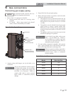
2. The rear of the boiler has a 1 inch (25.4 mm) stainless steel
drain fitting and a 3/8 inch (9.8 mm) stainless steel vent line
for connection to the condensate trap.
3. Connect the 1 inch (25.4 mm) fitting to the 1 inch (25.4
mm) fitting on the condensate trap with the factory
supplied silicone hose. Secure the hose to the condensate
trap and the boiler using the factory supplied hose clamps.
4. Connect the 3/8 inch (9.8 mm) fitting to the 3/8 inch (9.8
mm) fitting on the condensate trap (shipped loose) with
the factory supplied silicone hose. Secure the hose to the
condensate trap and the boiler using the factory supplied
hose clamps.
5. The condensate trap must be installed at the same level or
below the boiler base.
6. The condensate trap is sized for a 1" PVC outlet connection
pipe.
7. Plug the wiring connection from the condensate trap into
the connector located on the back of the unit.
8. Slope condensate tubing down and away from the boiler
into a drain or condensate neutralizing filter. Condensate
from the Crest will be slightly acidic (typically with a pH
from 3 to 5). Install a neutralizing filter if required by local
codes.
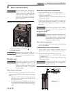
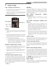
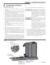
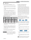
A neutralizer kit (FIG. 8-1) is available from the factory
(KIT30097). The neutralizer kit must be placed on a surface
that is a minimum of 3 inches lower than the condensate
trap with field supplied piping (vacuum break) installed
between the condensate trap and the neutralizer kit.
Use materials approved by the authority
having jurisdiction. In the absence of
other authority, PVC and CPVC pipe
must comply with ASTM D1785 or D2845.
Cement and primer must comply with
ASME D2564 or F493. For Canada use
CSA or ULC certified PVC or CPVC pipe,
fittings, and cement.
10. A condensate removal pump is required if boiler is below
the drain. When installing a condensate pump, select one
approved for use with condensing boilers and furnaces.
The pump should have an overflow switch to prevent
property damage from condensate spillage. The switch
should be wired to the auxiliary device proving switch
terminals on the low voltage connection board.
NOTICE
NOTICE
To allow for proper drainage on large
horizontal runs, a second line vent may
be required and tubing size may need to
increase to 1 inch (25 mm).
The condensate line must remain
unobstructed, allowing free flow of
condensate. If condensate is allowed to
freeze in the line or if the line is obstructed
in any other manner, condensate can exit
from the boiler tee, resulting in potential
water damage to property.
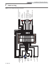
CONDENSATE TRAP
SAME LEVEL OR BELOW
BOILER BASE
NEUTRALIZER KIT
(OPTIONAL)
3” MINIMUM BELOW
CONDENSATE TRAP
FLOOR DRAIN
OR DRAIN PAN
DETAIL
VACUUM
BREAK
IMG00174
Figure 8-1 Condensate Disposal
9. Do not expose condensate line to freezing temperatures.
39