


Installation & Operation Manual
4 Sidewall direct venting (continued)
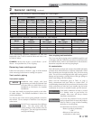
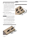
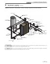
2. Place wall penetrations to obtain minimum clearance
of 12 inches (305 mm) between vent pipe and adjacent
air inlet, as shown in FIG. 4-4 for U.S. installations. For
Canadian installations, provide clearances required by
CSA B149.1 Installation Code.
3. The air inlet of a Crest is part of a direct vent
connection. It is not classified as a forced air intake
with regard to spacing from adjacent boiler vents.
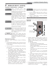
12" MIN
36" MIN
48" MAX
12"
36"
12"
AIR
VENT
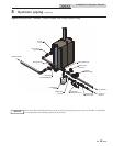
Figure 4-4 Multiple Vent Terminations (must also
comply with Figure 4-1)
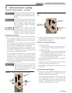
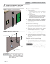
DIRECT VENT TERMINATIONS
Air Inlet Vent Termination
Dryer Inlet Straight
90° Elbow Mitered
23° Elbow
Figure 4-5 Direct Vent Terminations
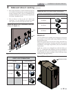
ROOM AIR (DIRECT EXHAUST TERMINATIONS)
Vent Termination
23° Elbow
45° Elbow
90° Elbow
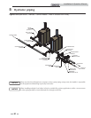
Figure 4-6 Room Air (Direct Exhaust Terminations)
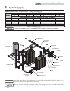
Room air
AIR INLET COVER
Figure 4-7 Room Air Installation
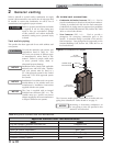
The Crest boiler may be installed with a single pipe carrying the
flue products to the outside while using combustion air from
the equipment room.
Follow the requirements in the General Venting, Sidewall Direct
Venting, and Vertical Direct Venting sections for vent material
specifications, vent length requirements, and vent termination
requirements.
Install the air inlet cover (shipped loose with the boiler) per
FIG. 4-7. Combustion and ventilation air must be supplied to
the equipment room per the requirements on pages 12 and 13
of this manual for proper operation of the Crest boiler when
utilizing the single pipe method.
23