


Installation & Operation Manual
5 Hydronic piping
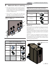
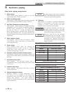
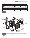
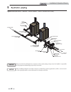
Near boiler piping components
1. Boiler piping:
Boiler system piping should be sized per the pipe
requirements listed in Tables 5A and 5C.
2. Boiler circulating pump:
Field supplied. When using Primary/Secondary piping the
boiler circulating pump should be sized per Table 5A.
3. Hot Water Generator circulating pump:
Field supplied. When installed in a Primary/Secondary
arrangement, the Crest requires an additional pump for
the Hot Water Generator Loop. The pump should
be sized per Table 5A. Consult the indirect water
heater operating guide to determine flow characteristics
for the selected product used. The pump’s total flow and
heat requirements are the sum of the boiler and the indirect
water heater.
4. Boiler isolation valves:
Field supplied. Full port valves are required. Failure
to use full port valves could result in a restricted flow
rate through the boiler.
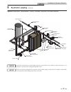
5. Check valves:
Field supplied. Check valves are required for
installation as shown in FIG.’s 5-2 and 5-3. Failure to
install check valves could result in a reverse flow
condition during pump(s) off cycle.
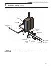
6. Domestic indirect hot water isolation valves:
Field supplied. Full port valves are required. Failure to use
full port valves could result in a restricted flow rate through
the boiler.
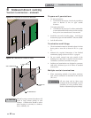
7. Anti-scald mixing valve:
Field supplied. An anti-scald mixing valve is
recommended when storing domestic hot water above
115°F (46°C).
8. Pressure relief valve:
Factory supplied. The pressure relief valve is sized to
ASME specifications.
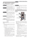
9. System temperature sensor:
Lochinvar supplies a system temperature sensor.
The sensor is to be installed in the heating loop
downstream from the boiler hot water piping and
heating loop junction. The sensor should be
located far enough downstream to sense system diluted
water temperature.
NOTICE
A system supply sensor (factory supplied)
MUST BE installed with Primary/Secondary
systems for proper boiler operation.
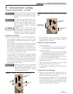
10. Y-Strainer:
Field supplied. A Y-strainer or equivalent multipurpose
strainer is recommended at the inlet of the heat
exchanger to remove system particles from older
hydronic systems and protect newer systems.
26
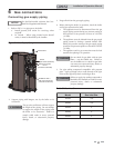
ƽ CAUTION
The maximum allowable water flow rate
through a single Crest boiler is 350 GPM.
Exceeding this flow rate will result in damage
to the heat exchanger and/or piping.
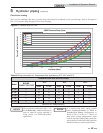
NOTICE
Reference Table 5B1 for the minimum
recommended flow rate through a single
Crest boiler at full fire to maintain a 80°F
temperature rise. Reference Table 5B2 for
the absolute minimum flow rate through a
single Crest boiler.
TEMPERATURE RISE APPLICATIONS
MODEL FLOW RATE (GPM)
FB(N,L)1500 35
FB(N,L)2000 46
FB(N,L)2500 58
FB(N,L)3000 70
FB(N,L)3500 81
[Based on 80°F Temperature Rise]
Table 5B1 Minimum Flow Rate with the Boiler at Full Fire
ABSOLUTE MINIMUM FLOW RATE
MODEL FLOW RATE (GPM)
FB(N,L)1500 25
FB(N,L)2000 25
FB(N,L)2500 25
FB(N,L)3000 25
FB(N,L)3500 45
Table 5B2 Absolute Minimum Flow Rate