


46
Installation & Operation Manual
General
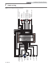
How the boiler operates
The Crest uses an advanced stainless steel heat exchanger
and electronic control module that allows fully condensing
operation. The blowers pull in air and push flue products out
of the boiler through the heat exchanger and flue piping. The
control module regulates blower speeds to control the boiler
firing rate. The gas valves sense the amount of air flowing
into the boiler and allow only the right amount of gas to flow.
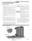
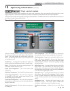
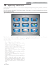
How the control modules operate
The Crest boiler is equipped with a SMART TOUCH control
module. The SMART TOUCH control module receives
inputs from boiler sensors and external devices. The control
module activates and controls the blowers and gas valves
to regulate heat input and switches the boiler, Hot Water
Generator (HWG), and system pumps on and off as needed.
The user programs the control module to meet system needs
by adjusting control parameters. These parameters set
operating temperatures and boiler operating modes.
Control inputs and outputs
Enable
This input tells the boiler to provide water for space heating.
Hot Water Generator (HWG) tank thermostat
This input tells the boiler to provide water for heating an
indirect HW tank.
0 - 10V BMS input (set point or power)
The Crest can be controlled by a Building Management
System (BMS) using a 0 - 10 VDC signal. The control can be
configured by the installer to use this signal to either control
set point or firing rate.
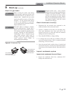
0 - 10V System Pump speed input
When a variable speed system pump is used, and there is a
0 - 10V signal available from the pump speed control, this
signal may be connected to the boiler. Doing so will allow
the boiler to anticipate changes in the BTU’s needed by the
system as the system flow changes, and therefore, help the
boiler to maintain the desired system temperature. Connect
the - input terminal to the COM or - output terminal on the
pump speed control, and the + input terminal to the 0 - 10V
or + output terminal on the pump speed control. Note that
the voltage on these inputs must never go below ground.
HWG priority
The SMART TOUCH control module allows connection of a
HW thermostat or sensor to the low voltage connection board.
When the HW thermostat or sensor calls for heat, the control
module activates the HW pump, shuts down the boiler pump,
and immediately sets the target outlet water temperature to
180°F (82.2°C).
This provides automatic priority heat allocation to the HW
Generator for maximum response and recovery. The HW
pump continues for 60 seconds after the heating cycle to deliver
the most possible heat. The control module can be programmed
to limit the firing rate of the boiler during a HW call for heat.
Controlling sensor
The control module is programmed to use the outlet sensor
as the control sensor by default. If a system supply sensor
is connected, the control automatically uses it as the control
sensor. The control module may be programmed to use the inlet
sensor as the control sensor instead. In this case, the control will
use the system return sensor if it is connected.
Anti-cycling
After a space heating demand has been satisfied, the control will
delay the next space heating call for a set time period (time is
adjustable by the installer). The time delay will be bypassed if
the inlet water temperature drops too far during the delay.
Boiler, system, and HW pump control
When a space heating call for heat starts and no HWG call is on,
the boiler pump is turned on. The system pump will turn on
also if it is programmed to do so. If a HWG call for heat is on,
the boiler pump will wait to turn on until just before the HWG
pump turns off. After the space heating call for heat ends, the
boiler pump will run for an additional period of time.
When a HWG call for heat starts, the HWG pump is turned on.
If a space heating call for heat is on, the boiler pump will turn
off a few seconds after the HWG pump turns on.
Louver
When the boiler needs to control combustion air louvers,
connect a 24 VAC louver relay to the two (2) Louver Relay
terminals. Connect the Louver End Switch to the Louver
Proving Switch input on the Low Voltage Connection Board.
Temperature control
Modulation
The Crest is capable of modulating its firing rate from a
minimum of 4 - 6% (model specific) to a maximum of 100%.
The firing rate is dictated by the call for heat (i.e., space heating
or hot water generation), the heating load, ramp delay (if
enabled), and various other temperature limitations.
10 Operating information