


Installation & Operation Manual
Low voltage connections
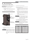
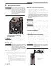
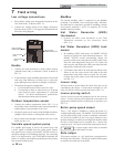
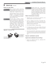
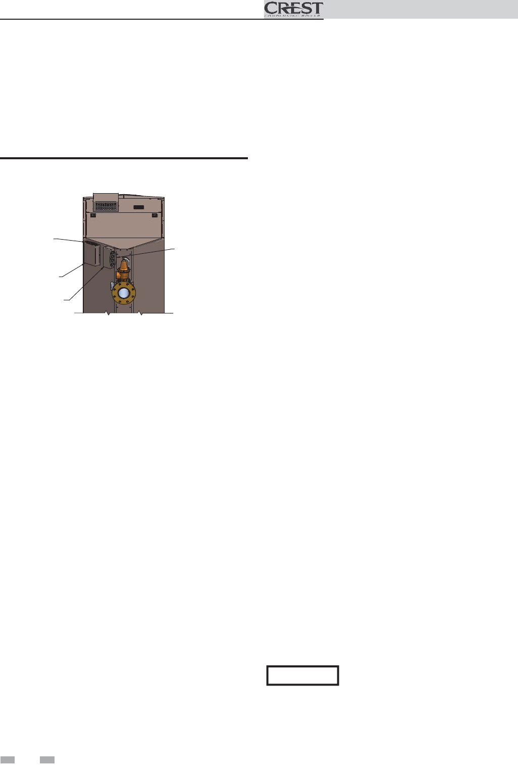
1. Route all low voltage wires through the knockouts in the
rear of the boiler, as shown in FIG. 7-2.
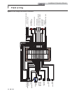
2. Connect low voltage wiring to low voltage connection
board as shown in FIG. 7-3 on page 38 of this manual and
the boiler wiring diagram.
LINE VOLTAGE
J-BOX
LOW VOLTAGE
J-BOX
LOW VOLTAGE
WIRING KNOCKOUTS
LINE VOLTAGE
WIRING KNOCKOUTS
Figure 7-2 Routing Field Wiring
7 Field wiring
Enable
1. Connect the room thermostat or boiler enable contacts
(isolated contact only) to terminals 7 and 8, as shown in
FIG. 7-3.
2. If a thermostat is used, install the thermostat on the inside
wall away from influences of drafts, hot or cold water
pipes, lighting fixtures, television, sunlight, or fireplaces.
3. Thermostat anticipator (if applicable):
a. If connected directly to boiler, set for 0.1 amps.
b. If connected to relays or other devices, set to match
total electrical power requirements of connected
devices. See device manufacturers’ specifications
and thermostat instructions for details.
Outdoor temperature sensor
1. Connect the outdoor temperature sensor (FIG. 7-3) to
the Outdoor Sensor terminals on the connection board to
enable outdoor reset operation of the Crest.
2. Mount the sensor on an exterior wall, shielded from direct
sunlight or flow of heat or cooling from other sources.
3. Route sensor wires through a knockout at the rear of the
boiler (see FIG. 7-2).
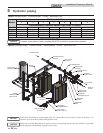
Variable speed system pump
If a variable speed pump is used in the primary loop, and
a 0-10V signal is available from the pump speed control,
this signal can be used by the SMART TOUCH control to
anticipate changes in the building heat load. By connecting
this 0 - 10V signal to the 0 - 10V SYS PUMP IN terminals, the
boiler (or cascade) can modulate up and down as the primary
flow increases and decreases.
ModBus
The RS-485 ModBus cable is connected to the ModBus
terminals. Use shielded, 2-wire twisted pair cable. If desired,
the shield can be connected to ground by installing a jumper
wire between terminals 1 and 3 on connector X5 on the
ModBus interface module.
Hot Water Generator (HWG)
thermostat
1. Connect the HWG tank thermostat to the Tank
Thermostat terminals on the connection board
(FIG. 7-3).
Hot Water Generator (HWG) tank
sensor
1. By installing a HWG tank sensor, the SMART TOUCH
control can perform the tank thermostat function. The
SMART TOUCH control automatically detects the
presence of this sensor, and generates a HWG call for heat
when the tank temperature drops 6°F (3°C) below the
tank set point, and finishes the call for heat when the tank
temperature reaches the tank set point.
2. A TST20015 sensor MUST be used with any indirect tank.
Failure to use the correct sensor will result in the tank
temperature being either above or below the set point.
Connect the correct sensor to the Tank Sensor terminals
(see FIG. 7-3).
Louver relay
If louvers need to operate before the boiler fires, they can be
controlled by this output. Connect these terminals to a 24V
relay coil, which is wired to operate the louvers (FIG. 7-3).
Louver proving switch
Louvers are used to provide combustion air for the room air
option. A louver proving switch should be connected to the
appropriate terminals and are verified prior to operation (see
FIG. 7-3).
Boiler pump speed output
This 0 - 10V output is available to control the speed of a
variable speed boiler pump. The SMART TOUCH control will
vary the speed of this pump in order to maintain a minimum
T (set by the installer, see the Crest Service Manual) across
the heat exchanger, as well as prevent high limit lockouts when
the flow in the primary loop is extremely low. Connect this
output to the 0 - 10V input on the boiler pump speed control.
Rate output
This output provides a 0 - 10V signal that is proportional to
the firing rate of the boiler. This may be used by a BMS system
to monitor the actual rate of the boiler.
36
NOTICE
A system supply sensor must be installed
for this feature to work.