


MS8200 / MS8300 Installation Manual - Page 7
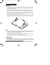
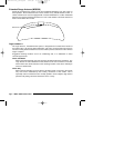
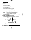
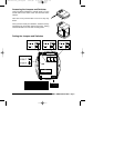
Extended Range Antenna (MS8300)
Plug the Extended Range Antenna into the
connector at the to of the Main unit and wrap
antenna wire around Extended Range
Antenna cable to prevent interference.
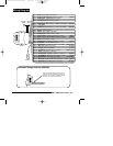
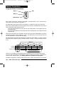
Pin 4 - Violet/yellow: Warn Away (-) input
Pin 1 - Red: Sensor power +12v output
Pin 3 - White/violet: Optional Sensor (-) input
Pin 1 - White/green: Door Lock (-) / Unlock +12v output
[500mA]*
Pin 2 - White
or
White/Orange: Armed (-) output [150mA]
Pin 8 - Gray/black: Sensor Defeat (-) input
Pin 9 - Yellow/white: Auxiliary Function 1 (+/-) output
[built-in relay]
Pin 13 - Violet: Ignition Key +12v input
Pin 1 - Black: Chassis Ground
Pin 3 - White/blue: Door Unlock (-) / Lock +12v output
[500mA]*
Pin 14 - Yellow/black: Auxiliary Function 2 (-) output [500mA]
Pin 2 - **not used**
Pin 11 - Orange: Siren +12v output
[1 Amp]
Pin 17 - Blue/red: Starter Disable Normally Open (-) output [500mA]
Pin 18 - Red/white: Secondary Power +12v input [20A fuse]
Pin 15 - Orange/Blue: Alarming / Horn Honk (-) output [500mA]
Pin 2 - Yellow: Door Trigger +12v input
Pin 16 - Black/white: Dome Light (+/-) output
[built-in relay]
Pin 10 - Red: Main Power +12v input [3A fuse]
Pin 5 - Blue: Normally Closed Starter Disable (-) output [500mA]
Pin 4 - Yellow/violet: Auxiliary Function 3 (-) output [500mA]
Pin 3 - White/brown: Hood / Trunk (-) input
Pin 6 - White: Door Trigger (-) input
Pin 7 - Yellow/green: Auxiliary Function 4 (-) output
[500mA]
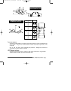
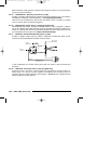
Logic
Sensor II
Override
Switch
Status
LED
Pin 12 - Red/Yellow: Parking Light (+/-) output
[built-in relay]
*for positive (+12v) polarity locking and unlocking max current is 150mA
Wiring Diagram
installation_rev3.qxd 7/26/99 6:07 PM Page 7